Software(XON/XOFF) Handshaking:

Each port can be independently configured for software handshaking. Software handshaking is normally used in communications links where the main data stream is one way, such as to a printer. The main sending device is expected to hold off its data when it receives the XOFF(13 Hex) character, and resume sending when it receives an XON(11 Hex). The main receiving device is expected to send the XOFF character if the buffer is full or it otherwise needs to hold off the data.

The 232BRC can be set to emulate either the main sending device or the receiving device. It can either supply the XON/XOFF handshake or stop sending data with the XON/XOFF. The port would normally be set to supply the XON/XOFF characters if it is connected to a fast sending device. It would be set to receive the XON/XOFF handshaking if the port is connected to the slower receiving device.

Port Connections

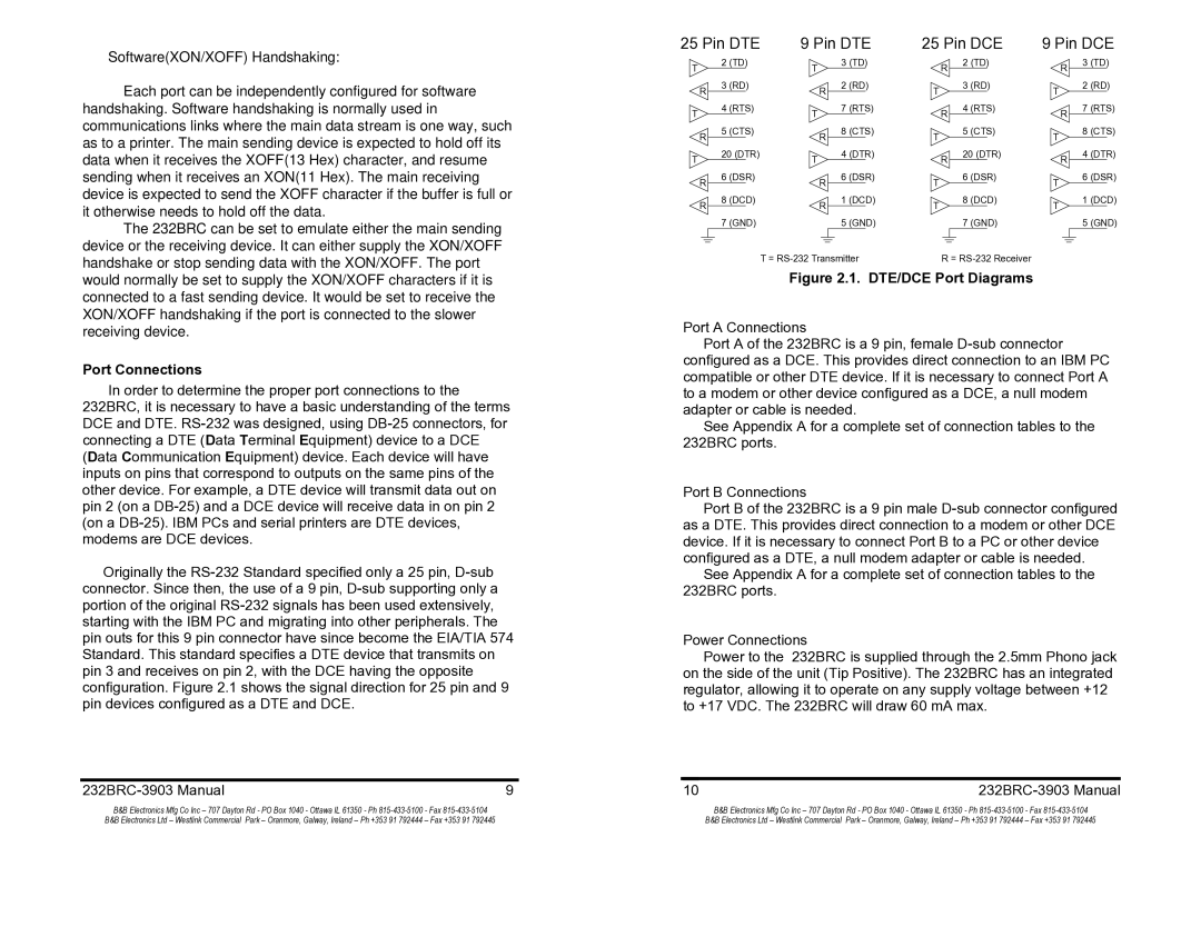
In order to determine the proper port connections to the 232BRC, it is necessary to have a basic understanding of the terms DCE and DTE. RS-232 was designed, using DB-25 connectors, for connecting a DTE (Data Terminal Equipment) device to a DCE (Data Communication Equipment) device. Each device will have inputs on pins that correspond to outputs on the same pins of the other device. For example, a DTE device will transmit data out on pin 2 (on a DB-25) and a DCE device will receive data in on pin 2 (on a DB-25). IBM PCs and serial printers are DTE devices, modems are DCE devices.

Originally the RS-232 Standard specified only a 25 pin, D-sub connector. Since then, the use of a 9 pin, D-sub supporting only a portion of the original RS-232 signals has been used extensively, starting with the IBM PC and migrating into other peripherals. The pin outs for this 9 pin connector have since become the EIA/TIA 574 Standard. This standard specifies a DTE device that transmits on pin 3 and receives on pin 2, with the DCE having the opposite configuration. Figure 2.1 shows the signal direction for 25 pin and 9 pin devices configured as a DTE and DCE.

232BRC-3903 Manual

9

25 Pin DTE

9 Pin DTE

25 Pin DCE

9 Pin DCE

T


2

(TD)

T


3

(TD)


R

2

(TD)


R

3

(TD)


R

3

(RD)

R

2

(RD)

T

3

(RD)

T

2

(RD)


T

4

(RTS)

T

7

(RTS)

R

4

(RTS)

R

7

(RTS)


R

5

(CTS)

R

8

(CTS)

T

5

(CTS)

T

8

(CTS)


T

20 (DTR)

T

4

(DTR)

R

20 (DTR)

R

4

(DTR)


R

6

(DSR)

R

6

(DSR)

T

6

(DSR)

T

6

(DSR)


8

(DCD)


1

(DCD)


8

(DCD)


1

(DCD)


R


R

T


T


7

(GND)


5

(GND)


7

(GND)


5

(GND)


T = RS-232 Transmitter


R = RS-232 Receiver


Figure 2.1. DTE/DCE Port Diagrams

Port A Connections

Port A of the 232BRC is a 9 pin, female D-sub connector configured as a DCE. This provides direct connection to an IBM PC compatible or other DTE device. If it is necessary to connect Port A to a modem or other device configured as a DCE, a null modem adapter or cable is needed.

See Appendix A for a complete set of connection tables to the 232BRC ports.

Port B Connections

Port B of the 232BRC is a 9 pin male D-sub connector configured as a DTE. This provides direct connection to a modem or other DCE device. If it is necessary to connect Port B to a PC or other device configured as a DTE, a null modem adapter or cable is needed.

See Appendix A for a complete set of connection tables to the 232BRC ports.

Power Connections

Power to the 232BRC is supplied through the 2.5mm Phono jack on the side of the unit (Tip Positive). The 232BRC has an integrated regulator, allowing it to operate on any supply voltage between +12 to +17 VDC. The 232BRC will draw 60 mA max.

10

232BRC-3903 Manual

B&B Electronics Mfg Co Inc – 707 Dayton Rd - PO Box 1040 - Ottawa IL 61350 - Ph 815-433-5100 - Fax 815-433-5104

B&B Electronics Mfg Co Inc – 707 Dayton Rd - PO Box 1040 - Ottawa IL 61350 - Ph 815-433-5100 - Fax 815-433-5104

B&B Electronics Ltd – Westlink Commercial Park – Oranmore, Galway, Ireland – Ph +353 91 792444 – Fax +353 91 792445

B&B Electronics Ltd – Westlink Commercial Park – Oranmore, Galway, Ireland – Ph +353 91 792444 – Fax +353 91 792445

Page 6
Image 6
B&B Electronics 232BRC manual Port Connections, DTE/DCE Port Diagrams

232BRC specifications

B&B Electronics is renowned for its high-quality industrial communication solutions, and one of its standout products is the B&B Electronics 232BRC. This device plays a crucial role in serial data communication, especially in environments where robust and reliable connections are essential.

The B&B Electronics 232BRC is a serial-to-serial converter that facilitates the connection and communication between devices that utilize different serial protocols. It serves as a bridge for devices that may not otherwise be compatible, enabling seamless data exchange in various applications, from industrial automation to telemetry systems.

One of the main features of the 232BRC is its ability to support both RS-232 and RS-422/485 protocols, making it versatile for use in multiple scenarios. The device is capable of automatic baud rate detection, which simplifies the setup process and ensures that users can quickly establish a connection without the need for extensive configuration. This feature is particularly beneficial in dynamic environments where devices may frequently be added or removed.

In addition to multi-protocol support, the 232BRC is engineered with built-in signal regeneration. This capability enhances data integrity by restoring signals that may have degraded during transmission, ensuring that the data received remains accurate and reliable. This feature makes it an ideal choice for long-distance communication, where signal attenuation can be a significant concern.

The device is also designed for ruggedness, featuring an industrial-grade housing that protects it from dust, moisture, and temperature variations that are common in factory settings. This durability ensures a long service life, reducing maintenance and replacement costs for organizations.

Moreover, the 232BRC offers extensive power options, including the ability to draw power directly from the data lines, which can simplify installation in environments where power sources are limited.

Advanced LED indicators provide users with real-time feedback on the status of the device, assisting in troubleshooting and ensuring smooth operations.

In summary, the B&B Electronics 232BRC is a highly efficient and reliable solution for serial communication challenges. Its support for multiple protocols, signal regeneration, rugged design, and user-friendly features make it an indispensable tool for industries that depend on consistent and accurate data transmission. Whether used in manufacturing, transportation, or remote monitoring, the 232BRC stands out as a preferred choice for professionals seeking dependable communications solutions.