ESP902E, ESP902, ESP901E specifications
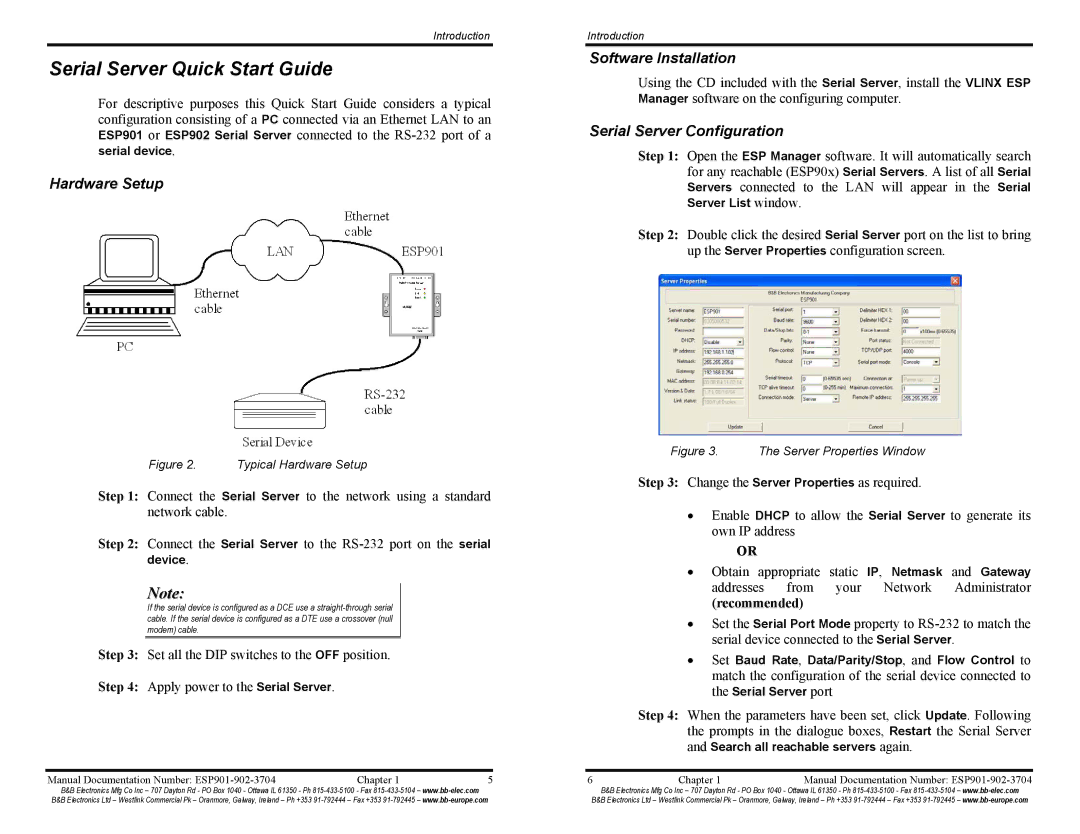
B&B Electronics offers a series of industrial-grade Ethernet serial servers known as the ESP901E, ESP902, and ESP902E. These devices are specifically designed to connect serial devices to an Ethernet network seamlessly, enabling effective communication and data transfer across various applications.The ESP901E is engineered for single serial port applications, providing an easy and effective way to connect a serial device to a network. It supports various serial communication protocols, including RS-232, RS-422, and RS-485, making it versatile for a range of devices. One of its standout features is the ability to support 10/100 Mbps Ethernet connectivity, ensuring a reliable and high-speed network connection. Additionally, the ESP901E supports various network protocols, including TCP/IP and UDP, allowing users to integrate the device easily into their existing network infrastructure.
Moving to the ESP902, this model provides dual serial port capabilities, making it ideal for applications requiring the connection of multiple devices. Like the ESP901E, it supports common serial interfaces and offers the same 10/100 Mbps Ethernet connectivity. This flexibility enables it to cater to more complex systems where multiple serial devices need to be integrated into a single network environment. Furthermore, the ESP902 is equipped with features such as automatic baud rate detection, making configuration straightforward and reducing installation time.
The ESP902E enhances the capabilities of the ESP902 with additional features such as enhanced security protocols. It includes support for SSL and SSH, ensuring secure data transmission across the network. This added security layer is crucial for applications that handle sensitive information or require secure communication channels. The ESP902E maintains the user-friendly nature of its predecessors while integrating more advanced features suitable for modern industrial applications.
All three models boast rugged designs suitable for harsh environments, making them perfect for industrial applications without compromising performance. With an extensive operating temperature range and robust housing, these devices can withstand the rigors of factory floors and outdoor installations.
Overall, the ESP901E, ESP902, and ESP902E from B&B Electronics collectively serve to bridge the gap between serial communications and Ethernet networks, supporting various industrial applications while ensuring seamless integration, versatility, and security. Whether for simple single-port connections or more complex multi-port setups, these devices are designed to meet diverse connectivity needs with efficiency and reliability.

