Zlinx 485 specifications
B&B Electronics Zlinx 485 is a reliable and efficient wireless serial communication solution designed for industrial applications. This device facilitates robust data transmission over long distances, making it an ideal choice for environments where conventional wired connections may be impractical or cost-prohibitive.One of the main features of Zlinx 485 is its ability to operate over a wide distance, reaching up to 1 mile (1.6 km) in line-of-sight scenarios. This capability significantly enhances connectivity options for remote devices and sensors, which is particularly valuable in diverse industrial setups.
The Zlinx module is built on the 802.15.4 protocol and operates in the 900 MHz frequency band, which is known for its excellent propagation characteristics and minimal interference from other wireless devices. This technology ensures reliable communication even in challenging environments, making it suitable for applications in factories, warehouses, and outdoor settings.
Another crucial characteristic of the Zlinx 485 is its versatility. The device supports both point-to-point and point-to-multipoint configurations, allowing for flexible network designs that can accommodate a variety of communication needs. This adaptability simplifies integration into existing systems while offering the scalability necessary for future expansions.
Security is a priority, and the Zlinx 485 offers various encryption options to safeguard data transmissions. With features like frequency hopping and error detection, users can be assured of secure and reliable communication, thereby maintaining data integrity across the network.
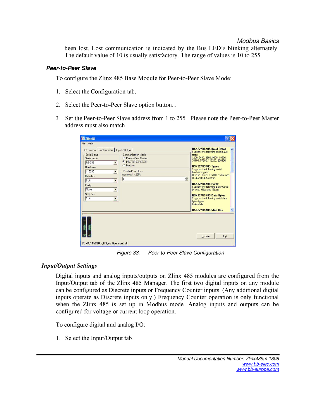
In terms of ease of use, the Zlinx 485 is designed with user-friendly interfaces that allow for straightforward installation and configuration. The modules can be easily configured using software tools provided by B&B Electronics, enabling users to set up communication parameters quickly without extensive technical expertise.
Additionally, the Zlinx 485 is robustly constructed to withstand harsh industrial environments. Its durable design and resistance to extreme temperatures make it a dependable choice for applications in demanding settings, ensuring longevity and consistent performance over time.
Overall, the B&B Electronics Zlinx 485 stands out as a powerful wireless solution that combines long-range communication, robust security features, versatility, and ease of use, making it an excellent choice for a variety of industrial applications. Its commitment to reliability and performance positions it as a leader in wireless serial communication technology.

