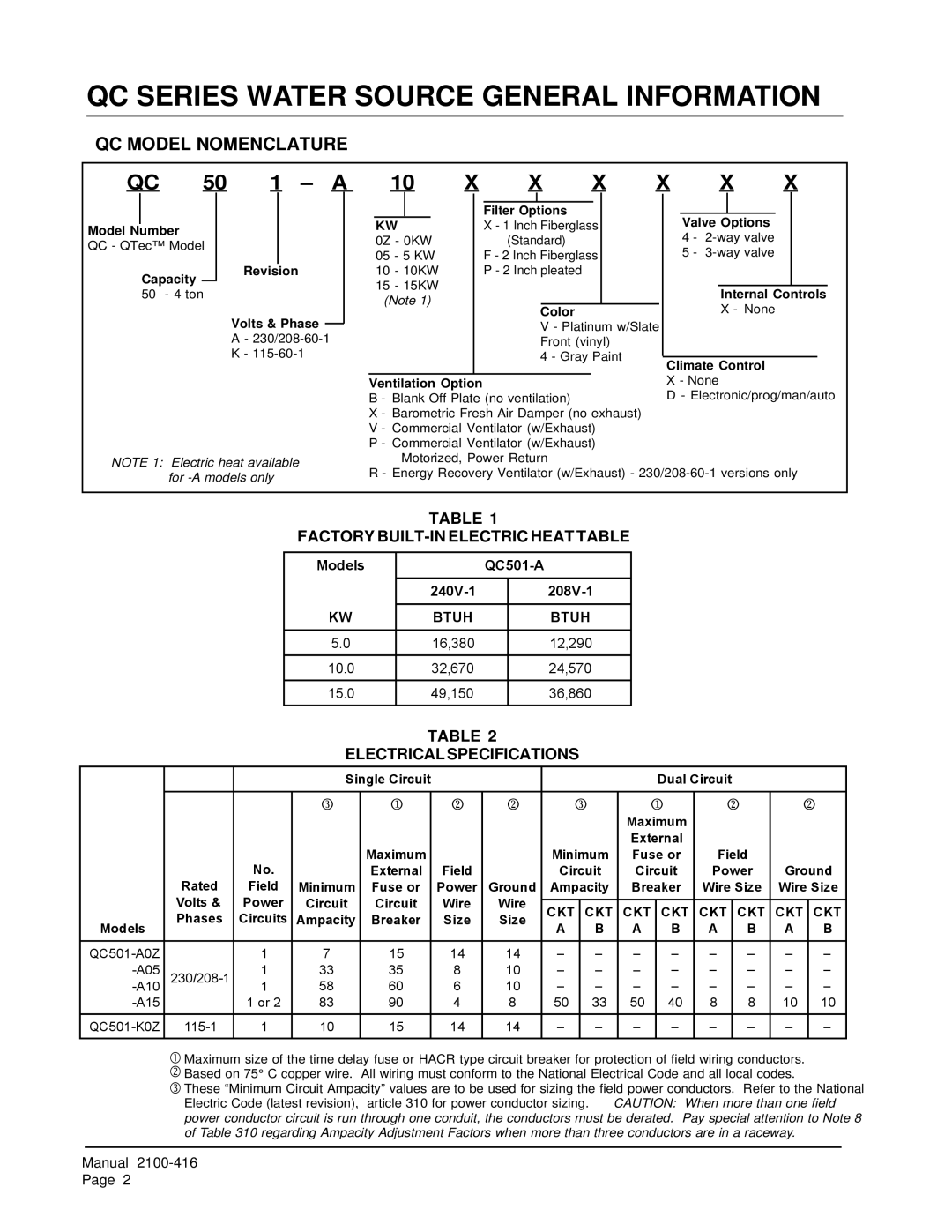
QC501 specifications
The Bard QC501 is an innovative piece of equipment designed specifically for quality control in various manufacturing processes. Known for its precision and efficiency, the QC501 serves multiple industrial sectors, including pharmaceuticals, food and beverage, cosmetics, and chemical manufacturing.One of the standout features of the Bard QC501 is its state-of-the-art measurement technology. It utilizes advanced sensors and automated systems to ensure highly accurate readings. This precision is critical for industries where even the smallest deviation can result in significant issues, such as compromised product safety or regulatory violations.
The QC501 incorporates a user-friendly interface that simplifies operation for technicians and quality control personnel. Its touchscreen display provides real-time data, allowing users to monitor processes effectively and make on-the-fly adjustments as needed. This responsiveness ensures that production standards are consistently met, enhancing overall efficiency.
Another notable characteristic of the Bard QC501 is its data logging capabilities. The device is equipped with comprehensive software that records, analyzes, and generates reports on quality metrics. This feature is invaluable for facilitating thorough audits and maintaining compliance with stringent industry regulations. By providing a digital trail of quality data, the QC501 empowers companies to demonstrate their commitment to quality assurance.
In terms of connectivity, the QC501 is designed to integrate seamlessly into existing production lines. It offers multiple connectivity options, such as Ethernet and USB ports, making it compatible with various systems. This flexibility allows businesses to enhance their existing quality control processes without a complete overhaul of their infrastructure.
Durability is another critical aspect of the QC501. Manufactured with robust materials, it is designed to withstand the rigors of industrial environments. This reliability reduces downtime due to equipment failure, ensuring that production schedules remain on track.
In summary, the Bard QC501 stands out for its precision measurement technology, user-friendly interface, comprehensive data logging, seamless connectivity, and rugged durability. This combination of features makes it an essential tool for industries striving to maintain high quality standards while optimizing production efficiency. Investing in the Bard QC501 is a proactive step toward enhancing overall product quality and ensuring compliance with regulatory standards.

