Page | Manual |
7 of 26 |
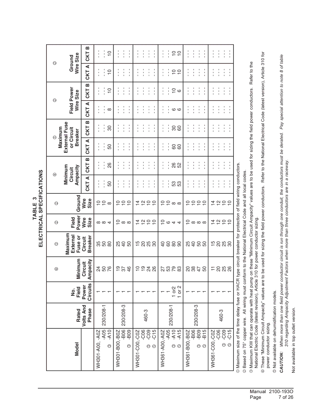
TABLE 3
ELECTRICAL SPECIFICATIONS
|
|
| 4 | 1 | 2 | 2 |
| 4 |
| 1 |
| 2 |
| 2 | |||||
|
|
|
|
|
| Maximum |
|
|
|
|
|
| |||||||
|
|
|
|
|
|
| Minimum |
|
|
|
|
|
| ||||||
|
|
|
| Maximum |
|
| External Fuse |
|
|
|
|
|
| ||||||
|
| No. |
|
|
| Circuit | or Circuit | Field Power | Ground | ||||||||||
Model |
|
| External | Field |
| ||||||||||||||
Rated |
|
| Ampacity | Breaker | Wire Size | Wire Size | |||||||||||||
Field | Minimum | Fuse or | Power | Ground | |||||||||||||||
|
|
|
|
|
|
|
|
|
|
|
|
| |||||||
| Volts And | Power | Circuit | Circuit | Wire | Wire |
|
|
|
|
|
|
|
|
|
|
|
| |
| CKT A | CKT B | CKT A | CKT B | CKT A | CKT B | CKT A | CKT B | |||||||||||
| Phase | Circuits | Ampacity | Breaker | Size | Size | |||||||||||||
|
|
|
|
|
|
|
|
|
|
|
|
| |||||||
|
|
|
|
|
|
|
|
|
|
|
|
|
|
|
|
|
|
| |
| 1 | 24 | 35 | 8 | 10 | - - - |
| - - - | - - - |
| - - - | - - - |
| - - - | - - - |
| - - - | ||
1 | 50 | 50 | 8 | 10 | - - - |
| - - - | - - - |
| - - - | - - - |
| - - - | - - - |
| - - - | |||
3 |
| 1 | 76 | 80 | 4 | 8 | 50 |
| 26 | 50 |
| 30 | 8 |
| 10 | 10 |
| 10 | |
|
|
|
|
|
|
|
|
|
|
|
|
|
|
|
|
|
|
| |
| 1 | 19 | 25 | 10 | 10 | - - - |
| - - - | - - - |
| - - - | - - - |
| - - - | - - - |
| - - - | ||
1 | 37 | 40 | 8 | 10 | - - - |
| - - - | - - - |
| - - - | - - - |
| - - - | - - - |
| - - - | |||
3 |
| 1 | 46 | 50 | 8 | 10 | - - - |
| - - - | - - - |
| - - - | - - - |
| - - - | - - - |
| - - - | |
|
|
|
|
|
|
|
|
|
|
|
|
|
|
|
|
|
|
| |
| 1 | 10 | 15 | 14 | 14 | - - - |
| - - - | - - - |
| - - - | - - - |
| - - - | - - - |
| - - - | ||
1 | 19 | 20 | 12 | 12 | - - - |
| - - - | - - - |
| - - - | - - - |
| - - - | - - - |
| - - - | |||
3 | 1 | 24 | 25 | 10 | 10 | - - - |
| - - - | - - - |
| - - - | - - - |
| - - - | - - - |
| - - - | ||
|
|
|
|
| |||||||||||||||
5 |
| 1 | 26 | 30 | 10 | 10 | - - - |
| - - - | - - - |
| - - - | - - - |
| - - - | - - - |
| - - - | |
|
|
|
|
|
|
|
|
|
|
|
|
|
|
|
|
|
|
| |
| 1 | 27 | 40 | 10 | 10 | - - - |
| - - - | - - - |
| - - - | - - - |
| - - - | - - - |
| - - - | ||
1 | 53 | 60 | 6 | 10 | - - - |
| - - - | - - - |
| - - - | - - - |
| - - - | - - - |
| - - - | |||
3 |
| 1 or2 | 79 | 80 | 4 | 8 | 53 |
| 26 | 60 |
| 30 | 6 |
| 10 | 10 |
| 10 | |
5 |
| 1 or 2 | 83 | 90 | 4 | 8 | 53 |
| 52 | 60 |
| 60 | 6 |
| 6 | 10 |
| 10 | |
|
|
|
|
|
|
|
|
|
|
|
|
|
|
|
|
|
|
| |
| 1 | 20 | 25 | 10 | 10 | - - - |
| - - - | - - - |
| - - - | - - - |
| - - - | - - - |
| - - - | ||
1 | 38 | 40 | 8 | 10 | - - - |
| - - - | - - - |
| - - - | - - - |
| - - - | - - - |
| - - - | |||
3 |
| 1 | 47 | 50 | 8 | 10 | - - - |
| - - - | - - - |
| - - - | - - - |
| - - - | - - - |
| - - - | |
5 |
| 1 | 50 | 50 | 8 | 10 | - - - |
| - - - | - - - |
| - - - | - - - |
| - - - | - - - |
| - - - | |
|
|
|
|
|
|
|
|
|
|
|
|
|
|
|
|
|
|
| |
| 1 | 11 | 15 | 14 | 14 | - - - |
| - - - | - - - |
| - - - | - - - |
| - - - | - - - |
| - - - | ||
1 | 20 | 20 | 12 | 12 | - - - |
| - - - | - - - |
| - - - | - - - |
| - - - | - - - |
| - - - | |||
3 | 1 | 25 | 25 | 10 | 10 | - - - |
| - - - | - - - |
| - - - | - - - |
| - - - | - - - |
| - - - | ||
|
|
|
|
| |||||||||||||||
5 |
| 1 | 26 | 30 | 10 | 10 | - - - |
| - - - | - - - |
| - - - | - - - |
| - - - | - - - |
| - - - | |
|
|
|
|
|
|
|
|
|
|
|
|
|
|
|
|
|
|
| |
1 Maximum size of the time delay fuse or HACR type circuit breaker for protection of field wiring conductors.
2 Based on 75° copper wire. All wiring must conform to the National Electrical Code and all local codes.
3 Maximum KW that can operate with heat pump on these "Minimum Circuit Ampacity" values are to be used for sizing the field power conductors. Refer to the National Electric Code (latest revision), Article 310 for power conductor sizing.
4 These “Minimum Circuit Ampacity” values are to be used for sizing the field power conductors. Refer to the National Electrical Code (latest version), Article 310 for power conductor sizing.
5 Not available on dehumidification models.
CAUTION: When more than one field power conductor circuit is run through one conduit, the conductors must be derated. Pay special attention to note 8 of table 310 regarding Ampacity Adjustment Factors when more than three conductors are in a raceway.
Not available in top outlet version.