MENU |
HOME |
Manual Index
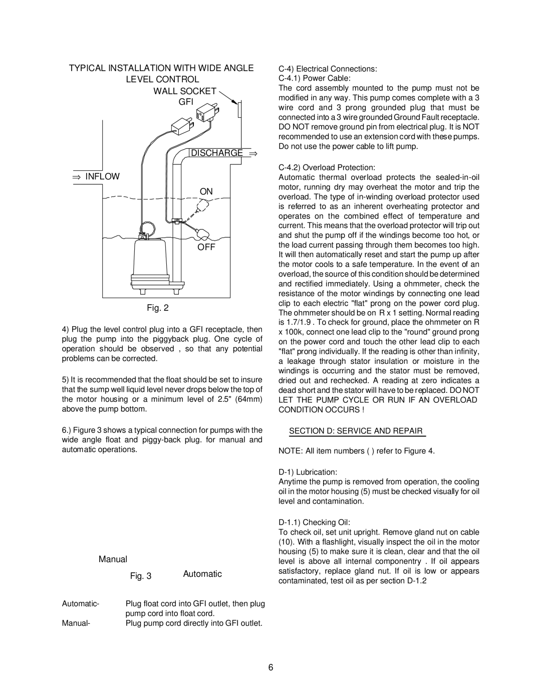
TYPICAL INSTALLATION WITH WIDE ANGLE
LEVEL CONTROL
WALL SOCKET
GFI
DISCHARGE ⇒
⇒INFLOW
ON
OFF
Fig. 2
4)Plug the level control plug into a GFI receptacle, then plug the pump into the piggyback plug. One cycle of operation should be observed , so that any potential problems can be corrected.
5)It is recommended that the float should be set to insure that the sump well liquid level never drops below the top of the motor housing or a minimum level of 2.5" (64mm) above the pump bottom.
6.) Figure 3 shows a typical connection for pumps with the wide angle float and piggy-back plug. for manual and automatic operations.
Manual |
| |
| Fig. 3 | Automatic |
Automatic- | Plug float cord into GFI outlet, then plug | |
| pump cord into float cord. | |
Manual- | Plug pump cord directly into GFI outlet. | |
The cord assembly mounted to the pump must not be modified in any way. This pump comes complete with a 3 wire cord and 3 prong grounded plug that must be connected into a 3 wire grounded Ground Fault receptacle. DO NOT remove ground pin from electrical plug. It is NOT recommended to use an extension cord with these pumps.
Do not use the power cable to lift pump.
C-4.2) Overload Protection:
Automatic thermal overload protects the
LET THE PUMP CYCLE OR RUN IF AN OVERLOAD CONDITION OCCURS !
SECTION D: SERVICE AND REPAIR
NOTE: All item numbers ( ) refer to Figure 4.
D-1) Lubrication:
Anytime the pump is removed from operation, the cooling oil in the motor housing (5) must be checked visually for oil level and contamination.
D-1.1) Checking Oil:
To check oil, set unit upright. Remove gland nut on cable (10). With a flashlight, visually inspect the oil in the motor housing (5) to make sure it is clean, clear and that the oil level is above all internal componentry . If oil appears satisfactory, replace gland nut. If oil is low or appears contaminated, test oil as per section
6