Remove the shutter tab by using a pair of side cutter pliers and file sharp edges flush with burner surface. This will permit the shutter to be locked securely.
Install the air shutter using the screw located below the pump. Adjust the shutter to the original air setting and tighten screw securely.
NOTICE On older burners, do not install the top shutter screw, it will interfere with the solenoid on the fuel unit.
To install a CleanCut fuel unit on a housing that has two top shut- ter mounting screw holes, make sure the screw is installed in the hole on the left that is closest to the front of the burner (air tube side).
Other Mounting Installations: The CleanCut Pump with a standard cord set or a PD Timer can be installed on the following burners: Carlin
Ducane ’DR’: 5/16” diameter hole will have to be drilled into the housing through the wire cavity.
Weil ’QB’: The valve coil blocks the air shutter screw. Allow enough slack in the cord set in order to pivot the valve coil away from the housing.
SYSTEM INSTALLATION REQUIREMENTS
ONE-PIPE SYSTEM
!DO NOT Install bypass plug - the shaft seal will rupture! Connect inlet line to pump inlet. Start burner. Arrange primary burner control for continuous operation during purging. Open bleed valve 1 turn CCW. Bleed unit until all air bubbles disap- pear. Notice: Hurried bleeding will impair efficient operation of unit. Tighten bleed valve securely.
The Clean Cut fuel unit may be installed with a Gravity or Lift Oil Supply System. The maximum allowable lift is 8 ft.
IMPORTANT: One pipe installations must be absolutely air tight or leaks or loss of prime may result. Bleed line and fuel unit completely. Bleed for 15 seconds after last air is seen from bleed / gauge port to be certain lines are air free.
L = line Length in Feet H = Head in Feet Q = Firing rate in GPH
3/8” Line | L = | 1/2” Line | L = | |
|
| .0086Q |
| .00218 Q |
*If tank is above pump, change – to +. Fittings, valves and filters will reduce total length allowed.
MAXIMUM 1 PIPE (H)
LIFT: 8FT
Figure 3
SK9858
TWO-PIPE SYSTEM
Remove 1/16” pipe bypass plug from plastic bag attached to unit. Remove 1/4” plug from return port. Insert
‘H’
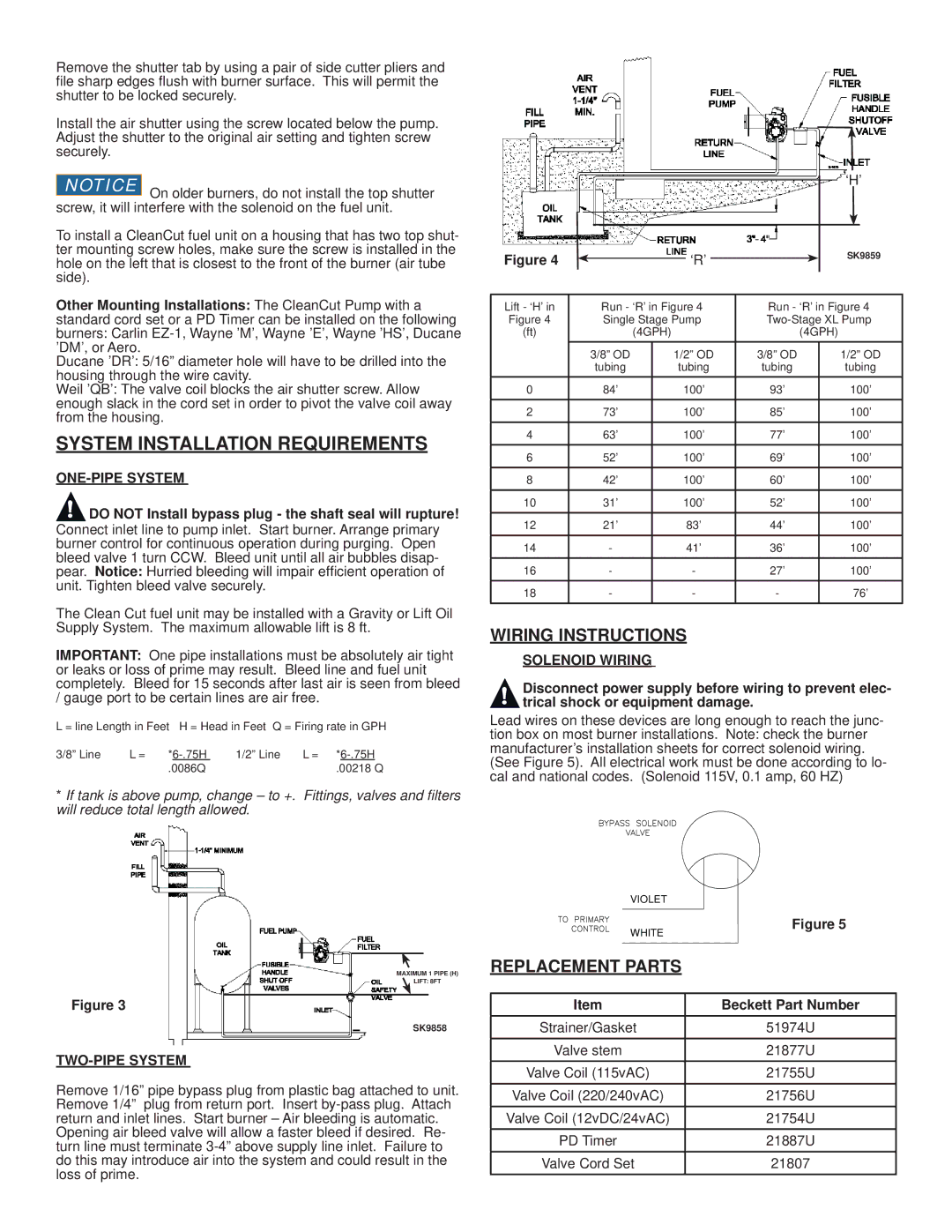
Figure 4 |
|
|
|
| ‘R’ |
|
|
|
| SK9859 |
|
|
|
|
|
|
|
|
| ||
|
|
|
|
|
|
|
|
| ||
Lift - ‘H’ in |
| Run - ‘R’ in Figure 4 | Run - ‘R’ in Figure 4 | |||||||
Figure 4 |
| Single Stage Pump | ||||||||
(ft) |
|
| (4GPH) |
| (4GPH) | |||||
|
| 3/8” OD |
| 1/2” OD | 3/8” OD |
|
| 1/2” OD | ||
|
| tubing |
| tubing | tubing |
|
| tubing | ||
0 |
| 84’ |
| 100’ | 93’ |
|
| 100’ | ||
2 |
| 73’ |
| 100’ | 85’ |
|
| 100’ | ||
4 |
| 63’ |
| 100’ | 77’ |
|
| 100’ | ||
6 |
| 52’ |
| 100’ | 69’ |
|
| 100’ | ||
8 |
| 42’ |
| 100’ | 60’ |
|
| 100’ | ||
10 |
| 31’ |
| 100’ | 52’ |
|
| 100’ | ||
12 |
| 21’ |
|
| 83’ | 44’ |
|
| 100’ | |
14 | - |
|
| 41’ | 36’ |
|
| 100’ | ||
16 | - |
| - |
| 27’ |
|
| 100’ | ||
18 | - |
| - |
| - |
|
| 76’ | ||
WIRING INSTRUCTIONS
SOLENOID WIRING
!Disconnect power supply before wiring to prevent elec- trical shock or equipment damage.
Lead wires on these devices are long enough to reach the junc- tion box on most burner installations. Note: check the burner manufacturer’s installation sheets for correct solenoid wiring. (See Figure 5). All electrical work must be done according to lo- cal and national codes. (Solenoid 115V, 0.1 amp, 60 HZ)
VIOLET
WHITE | Figure 5 |
| |
REPLACEMENT PARTS |
|
Item | Beckett Part Number |
Strainer/Gasket | 51974U |
Valve stem | 21877U |
Valve Coil (115vAC) | 21755U |
Valve Coil (220/240vAC) | 21756U |
Valve Coil (12vDC/24vAC) | 21754U |
PD Timer | 21887U |
Valve Cord Set | 21807 |