Section: Prepare the Burner for Start-up

Initial Air Settings

round surface of the shafts afterward.

If your burner was built for a specific OEM (Original

The test for proper alignment is to disengage the damper

motor from its shaft using the disengaging pin (Item G in

Equipment Manufacturer) application, the “Mfr’s

Figure 17) and rotate the damper plate to its full closed

Settings” label (see Figure 1) will indicate the application

position. The position indicator should point to 0° within

and the initial air settings made at Beckett. Please verify

+ 5° tolerance.


those settings using the following procedure.


If your burner was not built for a specified application,

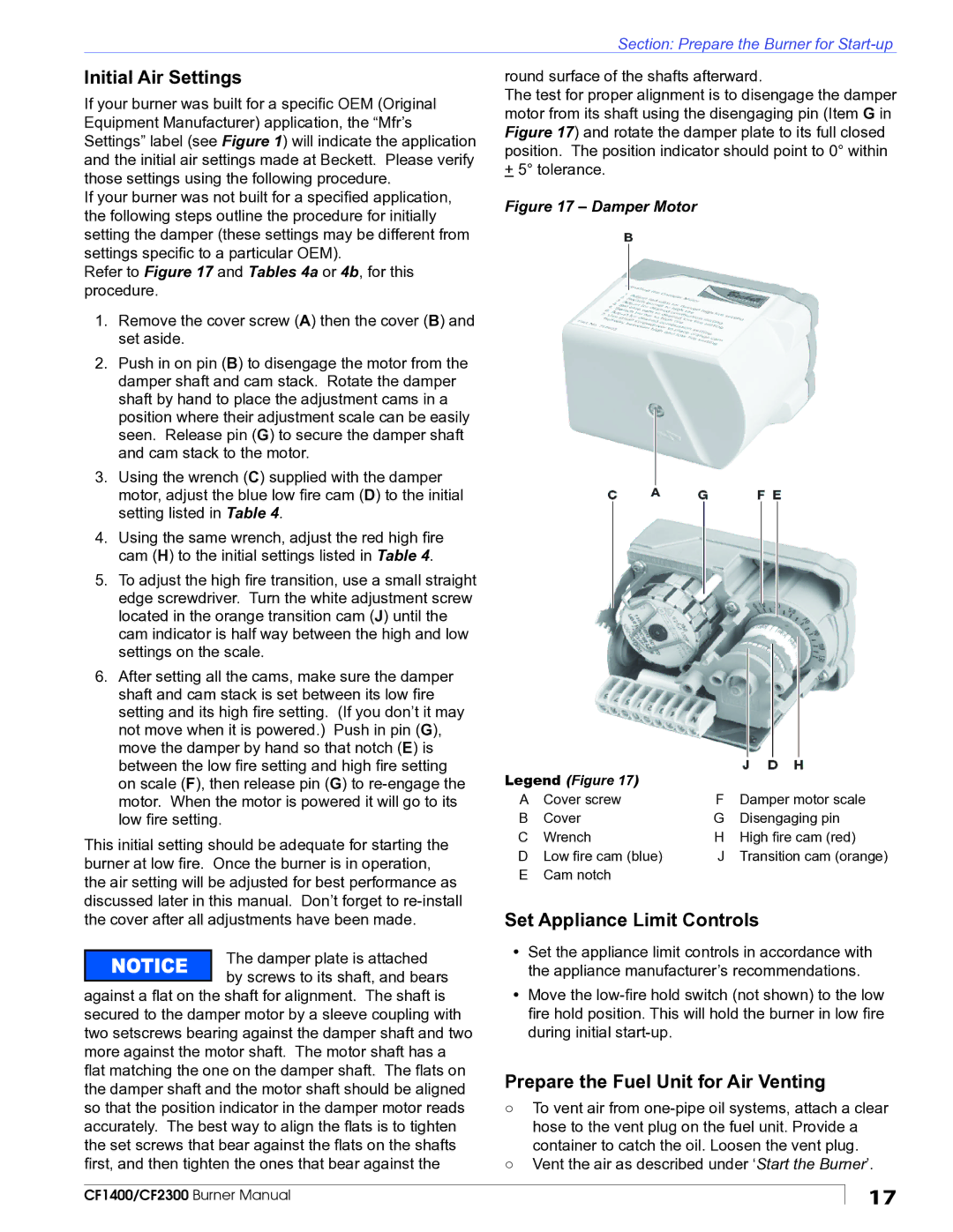
Figure 17 – Damper Motor


the following steps outline the procedure for initially


setting the damper (these settings may be different from


settings specific to a particular OEM).


Refer to Figure 17 and Tables 4a or 4b, for this


procedure.


1. Remove the cover screw (A) then the cover (B) and


set aside.


2. Push in on pin (B) to disengage the motor from the


damper shaft and cam stack. Rotate the damper


shaft by hand to place the adjustment cams in a


position where their adjustment scale can be easily


seen. Release pin (G) to secure the damper shaft


and cam stack to the motor.


3. Using the wrench (C) supplied with the damper


motor, adjust the blue low fire cam (D) to the initial


setting listed in Table 4.


4. Using the same wrench, adjust the red high fire


cam (H) to the initial settings listed in Table 4.


5. To adjust the high fire transition, use a small straight


edge screwdriver. Turn the white adjustment screw


located in the orange transition cam (J) until the


cam indicator is half way between the high and low


settings on the scale.


6. After setting all the cams, make sure the damper


shaft and cam stack is set between its low fire


setting and its high fire setting. (If you don’t it may


not move when it is powered.) Push in pin (G),


move the damper by hand so that notch (E) is


between the low fire setting and high fire setting

Legend (Figure 17)


on scale (F), then release pin (G) to re-engage the


motor. When the motor is powered it will go to its


A

Cover screw

F

Damper motor scale

low fire setting.

B

Cover

G

Disengaging pin

This initial setting should be adequate for starting the

C

Wrench

H High fire cam (red)

D

Low fire cam (blue)

J

Transition cam (orange)

burner at low fire. Once the burner is in operation,

E

Cam notch


the air setting will be adjusted for best performance as


discussed later in this manual. Don’t forget to re-install

Set Appliance Limit Controls

the cover after all adjustments have been made.


The damper plate is attached

y

Set the appliance limit controls in accordance with


the appliance manufacturer’s recommendations.


by screws to its shaft, and bears


Move the low-fire hold switch (not shown) to the low

against a flat on the shaft for alignment. The shaft is

y

secured to the damper motor by a sleeve coupling with


fire hold position. This will hold the burner in low fire

two setscrews bearing against the damper shaft and two


during initial start-up.


more against the motor shaft. The motor shaft has a


flat matching the one on the damper shaft. The flats on

Prepare the Fuel Unit for Air Venting

the damper shaft and the motor shaft should be aligned

so that the position indicator in the damper motor reads

○ To vent air from one-pipe oil systems, attach a clear

accurately. The best way to align the flats is to tighten


hose to the vent plug on the fuel unit. Provide a

the set screws that bear against the flats on the shafts


container to catch the oil. Loosen the vent plug.

first, and then tighten the ones that bear against the

○ Vent the air as described under ‘Start the Burner’.

CF1400/CF2300 Burner Manual

17

Page 17
Image 17
Beckett CF1400 manual Initial Air Settings, Set Appliance Limit Controls, Prepare the Fuel Unit for Air Venting

CF1400 specifications

Beckett has long been a household name in the heating and oil burner industry, renowned for producing equipment that excels in efficiency, reliability, and innovation. Among its impressive range of products, the CF1400 and CF2300 models stand out as exceptional offerings in the category of oil burners.

The Beckett CF1400 is designed for residential applications, delivering a robust performance that satisfies heating needs while minimizing energy consumption. This model is equipped with advanced technology that ensures precise fuel atomization, which translates into cleaner combustion and lower emissions. With adjustable combustion settings, users can optimize the burner for different home heating systems, ensuring peak performance regardless of the conditions.

In contrast, the CF2300 model is engineered for larger residential or light commercial setups. This powerhouse of a burner leverages enhanced fuel delivery systems and cutting-edge control features that allow for efficient operation and maintenance. Its design incorporates a heat exchanger that maximizes heat transfer, resulting in improved energy efficiency. Beckett’s commitment to quality is evident in its use of durable materials, ensuring that these units offer longevity and consistent performance over time.

Both models share several key technologies and characteristics. They are compatible with various heating oil types and can accommodate different fuel tank arrangements. The burners feature adjustable air settings, allowing for easy tuning to achieve optimal combustion performance. The CF1400 and CF2300 are also characterized by quiet operation, ensuring homeowners can enjoy a warm environment without disruptive noise levels.

Safety is paramount in the design of the CF series. Each unit comes equipped with safety controls that prevent overheating and other potential hazards, providing peace of mind to users. Furthermore, installation is user-friendly, and regular maintenance is simplified, reducing service costs and extending the lifespan of the burners.

The Beckett CF1400 and CF2300 models exemplify the brand's dedication to technological advancement and user-centric design. With their combination of efficiency, reliability, and cutting-edge features, these oil burners continue to be preferred choices for homeowners looking to improve their heating systems. Whether for residential or light commercial use, these models provide dependable heating solutions that align with modern energy standards.