Table 2 - Air tube capacities vs firebox pressure

Firebox

CF500

CF800

CF500

CF800


Tube

Tube

Tube

Tube

Tube

Tube

pressure

(in w.c.)

KK

KH

KJ

KK

KH

KJ

No reserve air

10% Turndown


0.0”

5.50

7.00

8.00

4.95

6.30

7.20

0.1”


4.27

5.62

6.75

4.75

6.25

7.50

0.2”


3.60

4.95

6.07

4.00

5.50

6.75

0.3”


3.15

4.00

5.62

3.50

4.50

6.25

0.4”


2.47

3.37

4.95

2.75

3.75

5.50

0.5”


1.80

2.70

4.50

2.00

3.00

5.00

Note: The above ratings may vary 5% due to variations in actual job conditions.

Mount the burner

Protect the Air Tube From

Overheating

Overheating could cause damage to the air tube and other combustion components lead- ing to equipment malfunction and impaired combustion performance.

yThe end of the air tube must not extend into the com- bustion chamber unprotected unless it has been facto- ry-tested and specified by the appliance manufacturer.

yPosition the end of the air tube 1/4” back from flush with the refractory inside entry wall to prevent damage from overheating.

‰Stray Light

Protect Against Stray

Light Lockout

Failure to follow these instructions could cause loss of burner operation resulting in no heat, an unplanned process interruption, work stoppage and the potential for frozen plumbing or other cold weather property damage.

yThe control must detect a dark, no-flame condition in order to start the burner or it will hold in the stray light lockout mode.

yShield the burner from direct exposure to intense light.

‰Dust and Moisture

Protect Against Dust and

Moisture

Wet, dusty environments could lead to blocked air passages, corrosion damage to components, impaired combustion performance and result in asphyxiation, explosion or fire.

yThis burner is designed for clean, dry installations.

yElectrical controls are not protected against rain or sprayed water.

yKeep the installation clear of dust, dirt, corrosive va- pors, and moisture.

yProtective covers and more frequent maintenance may be required.

‰Mount flange(s) on air tube

yThis section does not apply to burners with welded flang- es.

yDo not install air tube on burner.

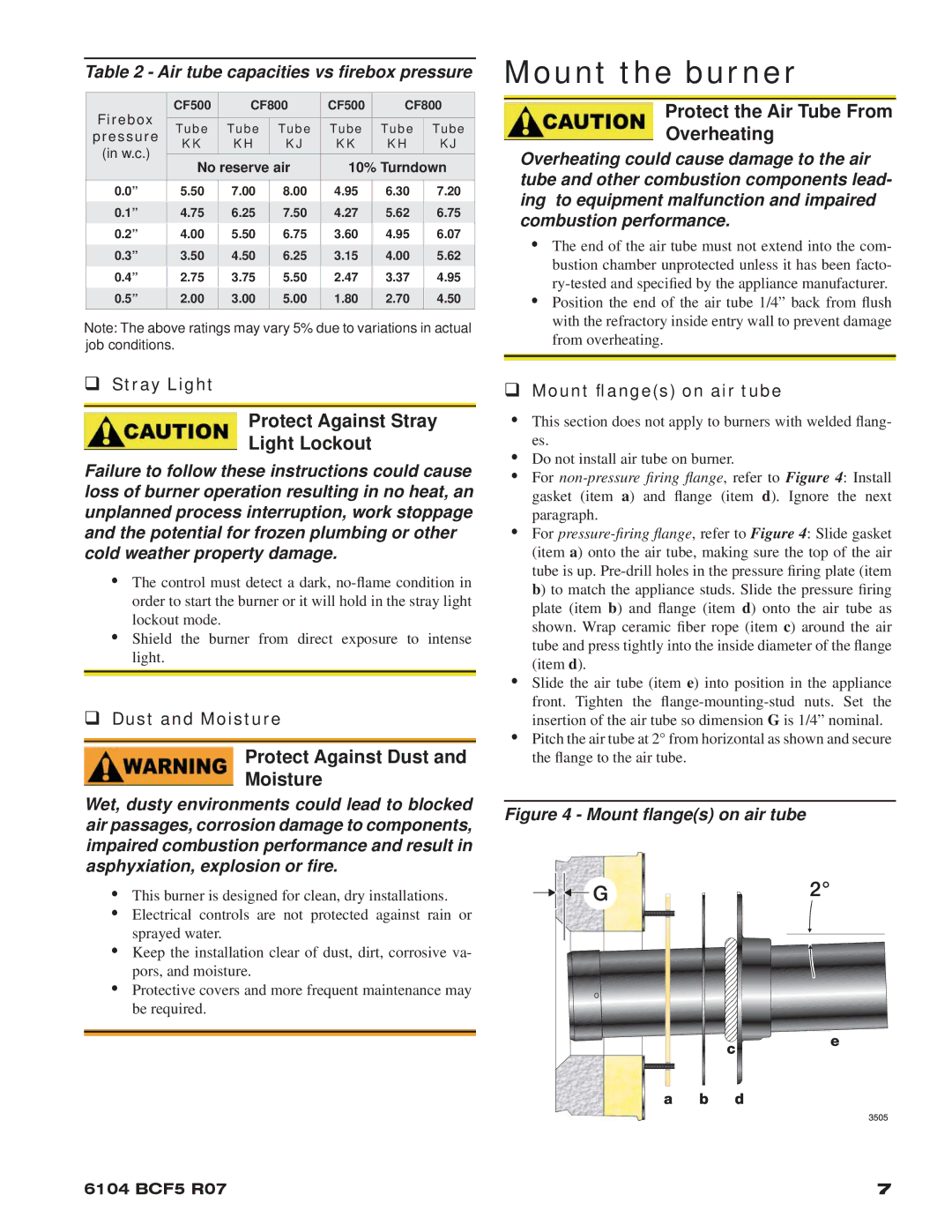
yFor non-pressure firing flange, refer to Figure 4: Install gasket (item a) and flange (item d). Ignore the next paragraph.

yFor pressure-firing flange, refer to Figure 4: Slide gasket (item a) onto the air tube, making sure the top of the air tube is up. Pre-drill holes in the pressure firing plate (item b) to match the appliance studs. Slide the pressure firing plate (item b) and flange (item d) onto the air tube as shown. Wrap ceramic fiber rope (item c) around the air tube and press tightly into the inside diameter of the flange (item d).

ySlide the air tube (item e) into position in the appliance front. Tighten the flange-mounting-stud nuts. Set the insertion of the air tube so dimension G is 1/4” nominal.

yPitch the air tube at 2° from horizontal as shown and secure the flange to the air tube.

Figure 4 - Mount flange(s) on air tube

6104 BCF5 R07

7

Page 7
Image 7
Beckett 800, CF500 manual Mount the burner, Protect the Air Tube From Overheating, Protect Against Stray Light Lockout

800, CF500 specifications

The Beckett CF500 and CF800 are advanced oil-fired boiler systems designed to provide reliable heating solutions for both residential and commercial applications. Known for their efficiency and cutting-edge technology, these models exhibit a variety of features that distinguish them in the heating market.

One of the standout characteristics of the Beckett CF500 and CF800 is their high combustion efficiency. Both models utilize a unique air control system that optimizes the air-fuel mixture, ensuring complete combustion and reducing emissions. This not only enhances performance but also benefits the environment by minimizing the carbon footprint.

The CF500 features a compact design, making it ideal for installations in tighter spaces. Its rugged construction ensures durability and longevity, often requiring less maintenance than competing systems. This model is equipped with advanced safety features, including a primary safety control and a backup safety circuit, ensuring secure operation in any conditions.

On the other hand, the CF800 is designed for larger applications, boasting a higher capacity and output. Its powerful burner system can handle higher BTU outputs, making it suitable for demanding heating needs. Like the CF500, the CF800 also features the advanced air-fuel management system, along with an innovative ignition system that guarantees quick starts and efficient operation.

Both models are engineered for ease of installation and maintenance. Their intuitive design allows for straightforward setup, while accessible components simplify routine servicing. Additionally, Beckett offers comprehensive support and resources, ensuring users can operate their systems effectively and efficiently.

Another notable technology integrated into these models is the noise reduction features. The quiet operation of both the CF500 and CF800 allows for a comfortable indoor environment, whether it's in a residential setup or a commercial facility.

In summary, the Beckett CF500 and CF800 represent a blend of efficiency, safety, and ease of use in oil-fired heating solutions. Their advanced features and technological innovations not only meet the heating demands of various applications but also support environmentally-conscious practices, making them an excellent choice for modern heating systems.