Fuel Line Installation

!CAUTION Do Not Use Teflon Tape

Damage to the pump could cause impaired burn- er operation, oil leakage and appliance soot-up.

Never use Teflon tape on fuel oil fittings.

Tape fragments can lodge in fuel line components and fuel unit, damaging the equipment and pre- venting proper operation.

Use oil-resistant pipe sealant compounds.

For fuel line installation, continuous lengths of heavy wall copper tubing are recommended. Always use flare fittings. Never use compression fittings.

Always install fittings in accessible locations. To avoid vibration noise, fuel lines should not run against the appliance or ceiling joists.

Fuel Line Valves and Filter

Install two high quality oil duty rated shutoff valves in accessible locations on the oil supply line. Locate one close to the tank and the other close to the burner, upstream of the filter.

NOTICE

For protection in the event of fire, some states require the shutoff valves to be a fusible-handle design. R.W. Beck- ett Corporation recommends this design as good industry practice for all installations.

NOTICE

To further protect the fuel supply system and reduce noz- zle orifice plugging with firing rates below 0.75 gph, a dual filtration system can be installed. This typically consists of a 50 micron primary filter, located near the fuel tank and a secondary filter rated for at least 10 microns located near the burner.

Also install a generous capacity filter, rated for 50 microns or less, inside the building between the fuel tank shutoff valve and the burner. Locate both the filter and the valve close to the burner for ease of servicing.

Inspect/Prepare Installation Site

Prepare the Burner

General

In most cases, the burner is ready to mount to the appliance. There can be situations where the burn- er needs to be reconfigured to perform properly in the appliance. Review the appliance manufactur- er’s specifications prior to installing to determine if any modification is required to properly configure the burner.

Instruction on how to perform the following burner preparation tasks can be found in the Professional Maintenance section.

Remove / install burner nozzle

Check head/air adjusting plate

Mount Burner on Appliance

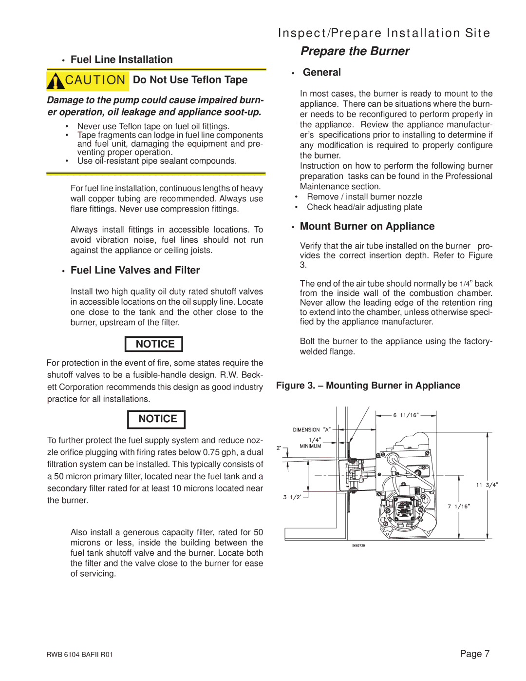
Verify that the air tube installed on the burner pro- vides the correct insertion depth. Refer to Figure 3.

The end of the air tube should normally be 1/4” back from the inside wall of the combustion chamber. Never allow the leading edge of the retention ring to extend into the chamber, unless otherwise speci- fied by the appliance manufacturer.

Bolt the burner to the appliance using the factory- welded flange.

Figure 3. – Mounting Burner in Appliance

Beckett

A2EA-65204 GPH 100-150 PSI 3450 RPM

3 GPH 150-200 PSI 3450 RPM

RWB 6104 BAFII R01

Page 7

Page 7
Image 7
Beckett AFII 100, FII 85, AFII 150 manual Prepare the Burner, Fuel Line Installation, Fuel Line Valves and Filter, General

FII 85, AFII 100, AFII 150 specifications

The Beckett AFII series, encompassing the AFII 150, AFII 100, and FII 85, represents a significant advancement in the realm of oil burners, particularly designed for residential and commercial heating applications. Around the heart of the AFII series lies a commitment to efficiency, reliability, and ease of installation, setting these models apart from traditional oil burner designs.

The AFII 150 model is particularly noteworthy for its impressive output capabilities, making it ideal for larger heating demands. It can produce up to 150,000 BTUs per hour, ensuring that even extensive spaces are heated effectively. The integrative SmartStart technology allows for quick ignition, enhancing energy efficiency and reducing fuel consumption. This model also features a robust construction that extends its lifespan and reduces maintenance needs, while its design minimizes carbon emissions, aligning with modern environmental standards.

The AFII 100 is designed for medium-sized applications, providing up to 100,000 BTUs per hour. Like the AFII 150, it incorporates SmartStart technology to enhance ignition performance and efficiency. Additionally, it boasts an advanced air-fuel ratio control system that optimizes combustion, providing better heating efficiency and environmental performance. Ease of installation is a key characteristic of the AFII 100, with components designed for straightforward integration into existing heating systems.

On the other hand, the FII 85 model serves the low-end heating sector effectively, with an output of up to 85,000 BTUs per hour. Its compact design is perfect for residential applications where space can be a constraint. The FII 85 also integrates Beckett’s patented CleanFire technology, which helps to maintain low emissions and reduce the likelihood of soot build-up. This feature not only prolongs the burner’s life but also enhances the air quality in the indoor environment.

Each model in the AFII series comes equipped with a range of diagnostic features that facilitate ease of use and maintenance, ensuring the systems are running efficiently over their lifespan. The reliability of the Beckett AFII series is further augmented by its adherence to industry standards, guaranteeing safety and performance.

In summary, the Beckett AFII 150, AFII 100, and FII 85 models showcase a thoughtful fusion of technology and engineering aimed at delivering superior heating solutions. Their advanced ignition systems, optimized combustion technologies, and robust designs make them ideal candidates for diverse heating needs, confirming Beckett's commitment to quality and sustainability in the oil burner market.