B1800X, B1020, B1500X specifications
Behringer is a renowned name in the audio equipment industry, known for its innovative products that cater to a variety of sound needs. Among its impressive lineup, the Behringer B1500X, B1020, and B1800X stand out as essential tools for musicians, sound engineers, and audio enthusiasts alike. These models combine advanced technological features with robust design to deliver high-quality audio experiences.The Behringer B1500X is a powerful powered subwoofer that boasts a 15-inch cone driver. One of its main features is a Class-D amplifier that provides excellent efficiency, delivering a peak output of 600 watts. This subwoofer is designed to reproduce low frequencies with precision, making it an ideal choice for live performances, DJ setups, and home theater systems. The B1500X also features an integrated limiter, ensuring that distortion is minimized even at high volumes. Its versatile connectivity options, including XLR and TRS inputs, allow for seamless integration into various audio setups.
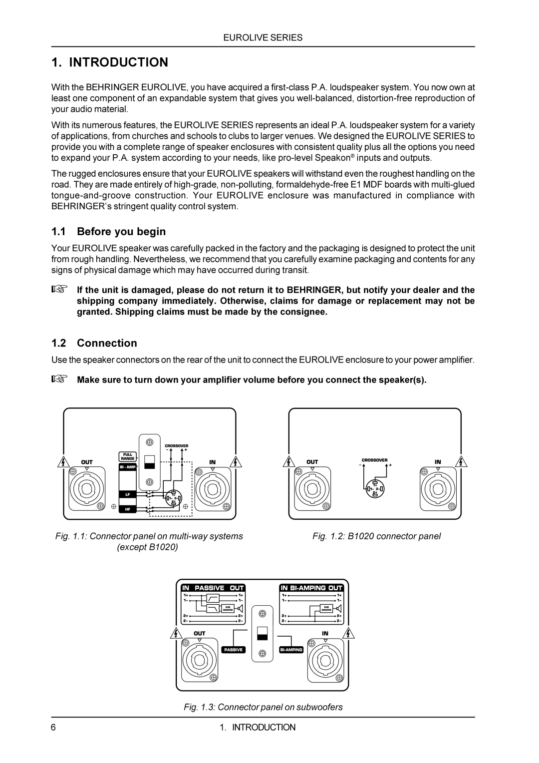
On the other hand, the Behringer B1020 is a compact yet powerful active two-way monitor speaker designed for studio use. It utilizes a 10-inch woofer for deep bass response and a 1-inch high-frequency compression driver for crisp treble. The B1020 includes a built-in 200-watt bi-amped amplifier, optimized to deliver balanced sound across the frequency spectrum. Its front-panel volume control and equalization options give users the flexibility to tailor their sound to fit different environments. This model's high-quality construction and acoustic design ensure accurate sound reproduction, making it a favorite for studio monitoring and home audio setups.
Lastly, the Behringer B1800X is another exceptional powered subwoofer featuring an 18-inch driver. This subwoofer excels in low-frequency performance, providing deep and powerful bass that can fill large venues. The B1800X comes equipped with a built-in state-of-the-art Class-D amplifier, capable of producing 800 watts peak output, catering to both live events and permanent installations. Additionally, it features an advanced digital signal processor that optimizes the audio signal, ensuring fidelity and clarity. With its robust cabinet design, the B1800X is built to withstand the rigors of touring while delivering consistent performance.
In summary, the Behringer B1500X, B1020, and B1800X exemplify the brand's commitment to quality and innovation. Each model serves unique purposes yet shares core technologies designed for optimum audio performance. Whether you are looking for an active monitor, a high-powered subwoofer, or reliable sound reproduction, these products provide exceptional features and lasting value in any audio application.