TUBE ULTRAGAIN T1953
8
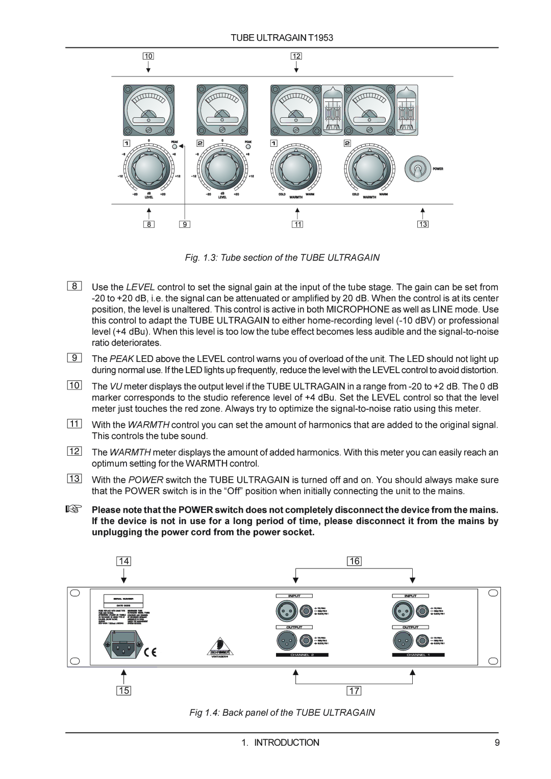
Fig. 1.3: Tube section of the TUBE ULTRAGAIN
Use the LEVEL control to set the signal gain at the input of the tube stage. The gain can be set from
9
The PEAK LED above the LEVEL control warns you of overload of the unit. The LED should not light up during normal use. If the LED lights up frequently, reduce the level with the LEVEL control to avoid distortion.
10
The VU meter displays the output level if the TUBE ULTRAGAIN in a range from
11
With the WARMTH control you can set the amount of harmonics that are added to the original signal. This controls the tube sound.
12
The WARMTH meter displays the amount of added harmonics. With this meter you can easily reach an optimum setting for the WARMTH control.
13
With the POWER switch the TUBE ULTRAGAIN is turned off and on. You should always make sure that the POWER switch is in the “Off” position when initially connecting the unit to the mains.
+Please note that the POWER switch does not completely disconnect the device from the mains. If the device is not in use for a long period of time, please disconnect it from the mains by unplugging the power cord from the power socket.
14
16
15
17
Fig 1.4: Back panel of the TUBE ULTRAGAIN
1. INTRODUCTION | 9 |