FOR MODELS
USER MANUAL
INTRODUCTION
Have you ever noticed your lights dim or flicker when you turn on your dishwasher or air conditioner? This common occurrence is attributed to an
A brownout is a period of insufficient
Effects: A brownout can deprive a computer of the power it needs to function, causing unwanted damage to your
Solution: A Belkin Uninterruptible Power Supply (UPS) unit protects against surges, spikes, swells,
IMPORTANT SAFETY INSTRUCTIONS
Thank you for purchasing the Belkin Uninterruptible Power Supply (UPS). It will provide you with the best protection for your connected equipment.
Please Save This Manual!
It includes important instructions for the safe use of this UPS and for obtaining factory service should the proper operation of the UPS come into question.
Please Save or Recycle the Packaging Materials!
The UPS shipping materials were designed with great care to provide protection from
Federal Communications Commission Interference Statement
This equipment has been tested and found to comply with the limits for a Class B digital device, pursuant to Part 15 of the FCC Rules. These limits are designed to provide reasonable protection against harmful interference in a residential installation. This equipment generates, uses, and can radiate radio frequency energy and, if not installed and used in accordance with the instructions, may cause harmful interference to radio communications. To assure continued compliance, use only shielded interface cables when connecting to computer or peripheral devices. Any changes or modifications not expressly approved by the party responsible for compliance could void the user’s authority to operate this equipment.
FRONT PANEL
Press the button longer than three seconds to turn the UPS on or off. Press the button less than three seconds to activate the UPS
Low Battery/Replace Battery | Fault/Overload |
On Line/On Battery | On/Off/Test |
OPERATION
Switch On
With the UPS plugged in, press and hold the on/off/test button for more than three seconds until the "ON LINE" LED lights up to switch the UPS on. The UPS will perform
Switch Off
Press and hold the on/off/test button for more than three seconds until the "ON LINE" or "ON BATTERY" LED goes off.
Self-Test
Use the
Note
During the
Silence
In " BACKUP" mode, push the on/off/test button less than three seconds to silence the audible alarm. (The function is void when under condition of "LOW BATTERY".)
Printer
Computer
Cash | Lamp | |
Register | ||
|
PRESENTATION
| LED | STEADY LIGHT |
| MEANING | |||
|
| BLINKING |
| ||||
|
|
|
|
|
| ||
|
|
|
|
|
|
|
|
| ON LINE/ |
| GREEN |
| Utility is normal. |
| |
| ON BATTERY |
|
|
|
| Utility is abnormal, supplies power to outlets |
|
|
|
|
|
|
| from battery source. |
|
|
|
|
|
|
|
|
|
|
|
|
|
|
| Battery capacity is low. The UPS will start |
|
| LOW BATTERY/ |
| YELLOW |
| shutdown. The unit sounds an audible alarm. |
| |
|
|
| 1. The LED flashes eight seconds. It means the |
| |||
| REPLACE |
|
|
| |||
|
|
|
|
|
| ||
|
|
|
|
| UPS is in the |
| |
| BATTERY |
|
|
|
|
| |
|
|
|
|
|
|
| |
|
|
|
|
|
| 2. The LED flashes more than 10 seconds. |
|
|
|
|
|
|
| It means the battery is bad or the charger |
|
|
|
|
|
|
| is at fault. |
|
|
|
|
|
|
|
|
|
| FAULT/ |
| RED |
|
| There is a problem with the UPS. The LED |
|
|
|
|
| will be lit continuosly and the unit will |
| ||
| OVERLOAD |
|
|
|
| sound an audible alarm for 10 seconds. |
|
|
|
|
|
|
| Battery ouput is drawing more power than |
|
|
|
|
|
|
| the UPS can provide. |
|
|
|
|
|
|
|
|
|
| SITE WIRING |
| RED |
|
| There is either no ground circuit or a |
|
| FAULT (IN REAR |
|
|
|
| ||
| PANEL) |
|
|
|
| reversed polarity in the building wiring. |
|
|
|
|
|
|
|
|
|
ALARM
Backup (Slow Alarm)
When in "BACKUP" mode, the GREEN LED illuminates and the UPS sounds an audible alarm. The alarm stops when the UPS returns to LINE NORMAL operation.
Low Battery (Rapid Alarm)
In "BACKUP" mode, when the battery energy runs low, the UPS beeps rapidly until the UPS shuts down from a depleted battery or returns to LINE NORMAL operation.
Overload (Continuous Alarm)
When the UPS is overloaded (the connected loads exceed the maximum rated capacity) the UPS emits a continuous alarm to warn of an overload condition. Disconnect nonessential equipment from the UPS to eliminate the overload.
Fault (10 Seconds Continuously)
When the output is shorted, the UPS emits a
REAR PANEL
Interface Port
Provides RS232 to relay the signal to support DOS, Windows, and other operating systems.
Phone/Fax/Modem/DSL or Network Protection Telephone/fax/modem lines are surge protected and provide complete safety for Internet connection. One input and one output allow two devices to be protected (i.e. modem and fax).
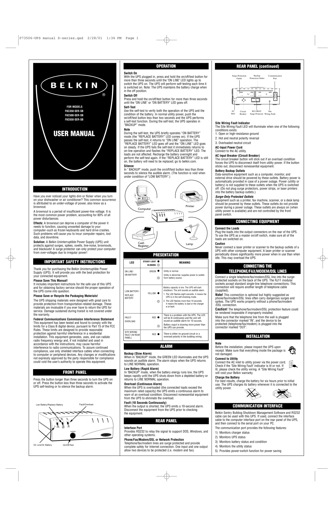
REAR PANEL (continued)
|
| Surge SurgeProtection |
|
|
| Backupup |
|
| Communication |
| |||||||||||||||||||||
|
| protectionOutletOutlet |
| Protection Outlet |
|
|
| PortPort |
| ||||||||||||||||||||||
|
|
|
|
|
|
|
|
|
|
|
|
|
|
|
|
|
|
|
|
|
|
|
|
|
|
|
|
|
|
|
|
|
|
|
|
|
|
|
|
|
|
|
|
|
|
|
|
|
|
|
|
|
|
|
|
|
|
|
|
|
|
|
|
|
|
|
|
|
|
|
|
|
|
|
|
|
|
|
|
|
|
|
|
|
|
|
|
|
|
|
|
|
|
|
|
|
|
|
|
|
|
|
|
|
|
|
|
|
|
|
|
|
|
|
|
|
|
|
|
|
|
|
|
|
|
|
|
|
|
|
|
|
|
|
|
|
|
|
|
|
|
|
|
|
|
|
|
|
|
|
|
|
|
|
|
|
|
|
|
|
|
|
|
|
|
|
|
|
|
|
|
|
|
|
|
|
|
|
|
|
|
|
|
|
|
|
|
|
|
|
|
|
|
|
|
|
|
|
|
|
|
|
|
|
|
|
|
|
|
|
|
|
|
|
|
|
|
|
|
|
|
|
|
|
|
|
|
|
|
|
|
|
|
|
|
|
|
|
|
|
|
|
|
|
|
|
|
|
|
|
|
|
|
|
|
|
|
|
|
|
|
|
|
|
|
|
|
|
|
|
|
|
|
|
|
|
|
|
|
|
|
|
|
|
|
|
|
ACAC | Circuit |
| RJ111/RJ45 |
| Site |
Inlet | Breaker |
| SurgeProtector |
| WiringFaultFault |
Inlet |
|
|
Site Wiring Fault Indicator
The Site Wiring Fault LED will illuminate when one of the following conditions exists:
1.Open or
2.Hot and neutral polarity reversal
3.Overloaded neutral circuit
Connect to the AC utility.
AC Input Breaker (Circuit Breaker)
The circuit breaker button will stick out if an overload condition forces the UPS to disconnect itself from utility power. If the button sticks out, disconnect nonessential equipment.
Battery Backup Outlets
Surge-Only Protected Outlets
Equipment such as a printer, fax machine, scanner, or a desk lamp should be powered by these outlets. These outlets do not provide power during a power outage. These outlets are always on (when utility power is available) and are not controlled by the front panel switch.
CONNECTING EQUIPMENT
Connect the Loads
Plug the loads into the output connectors on the rear of the UPS. To use the UPS as a master on/off switch, make sure all of the loads are switched on.
Caution
Never connect a laser printer or scanner to the backup outlets of a UPS with other computer equipment. A laser printer or scanner periodically draws significantly more power when in use than when idle. This may overload the UPS.
CONNECTING THE
TELEPHONE/FAX/MODEM/DSL LINES
Connect a single telephone/fax/modem/DSL line into the surge- protected sockets on the back of the UPS. The RJ11 modular sockets accept standard
Note! This connection is optional but highly suggested as phone/fax/modem/DSL lines often carry dangerous surges and spikes. The UPS works properly without a phone/fax/modem /DSL connection.
Caution! The telephone/fax/modem/DSL protection feature could be rendered inoperable if improperly installed.
Make sure that the telephone line from the wall is plugged into the connector marked "IN", and the device to be protected (telephone/fax/modem) is plugged into the connector marked "OUT".
INSTALLATION
Note
Before the installation, please inspect the UPS upon receipt. Make sure that everything inside the package is not damaged.
Connect to Utility
Connect the AC inlet to utility power via the power cord. Check if the "Site Wiring Fault" indicator is lit or not. If lit, please check the utility wiring. A “Site Wiring Fault” will void your Belkin warranty.
Charge the Battery
For best results, charge the battery for six hours prior to initial use. The UPS charges its battery whenever it is connected to the utility power.
COMMUNICATION INTERFACE
Belkin Sentry Bulldog Shutdown Management Software and RS232 cable can be used with this UPS. If used, connect the interface cable to the computer interface port on the rear panel of the UPS, and then connect to the serial port on your PC.
The communication port provides the following features:
1)Monitors charger status
2)Monitors UPS status
3)Monitors battery status and condition
4)Monitors the utility status
5)Provides