Important Safety Instructions
Thank you for purchasing the Belkin Uninterruptible Power Supply (UPS). It will provide you with the best protection for your connected equipment.
Please read this manual!
This manual provides safety, installation, and operating instructions that will help you obtain the highest performance and service life that the UPS has to offer.
Please save this manual!
It includes important instructions for the safe use of this UPS and for obtaining factory service should the proper operation of the UPS come into question.
Please save or recycle the packaging materials!
The UPS shipping materials were designed with great care to provide protection from transportation-related damage. These materials are invaluable if you ever have to return the UPS for service. Damage sustained during transit is not covered under the warranty.
Responsible Party:
Belkin Components, Ltd. | Belkin Components B.V. |
Unit 13 • Gatelodge Close • Round Spinney | Diamantlaan 8 • 2132 WV |
Northampton • Northants • NN3 8RX | Hoofddorp • The Netherlands |
United Kingdom | Tel: +31 (0) 235698765 |
Tel: +44 (0) 1604678300 | Fax: +31 (0) 235612694 |
Fax: +44 (0) 1604678330 | |
Introduction
Have you ever noticed your lights dim or flicker when you turn on your dishwasher or air-conditioning? This common occurrence is attributed to an under-voltage of power, also known as a BROWNOUT.
A brownout is a period of insufficient power-line voltage. It is the most common power problem, accounting for 80% of all power disturbances.
Effects: A brownout can deprive a computer of the power it needs to function, causing unwanted damage to your computer, such as frozen keyboards and hard drive crashes. Such problems will cause you to incur computer repairs, lost data, and downtime.
Solution: A Belkin Uninterruptible Power Supply (UPS) with Automatic Voltage Regulation (AVR). Typical "Stand-by" UPS units do not have AVR to increase the output voltage or decrease the output voltage to your computer. A surge protector can only protect your computer from over-voltages due to irregular power. Belkin UPS units protect against surges, spikes, swells, line-noise, brownouts, and blackouts!
Only a Belkin UPS with AVR can give your computer clean and consistent power at all times.
Note: There is no guarantee that interference to radio/TV will not occur in a particular installation. If this UPS causes interference to radio or television reception (this can be determined by turning the UPS power off and on), the user is encouraged to try to correct the interference by one or more of the following measures:
•Connect the equipment to an outlet on a circuit different from that to which the receiver is connected.
•Increase the separation between the equipment and the receiver.
•Reorient or relocate the receiving antenna.
Safety
CAUTION! To reduce the risk of electric shock, disconnect the UPS from the main power supply before installing a computer interface signal cable. Reconnect the power cord only after signaling interconnections have been made. CAUTION! The internal energy source (the battery) cannot be de-energized by the user. The output may be energized when the unit is not connected to a main power supply, thus, a shock hazard may be present.
CAUTION! (RISK OF ELECTRIC SHOCK) HAZARDOUS LIVE PARTS INSIDE THIS UNIT ARE ENERGIZED FROM THE BATTERY SUPPLY EVEN WHEN THE INPUT AC POWER IS NOT CONNECTED.
CAUTION! (RISK OF ELECTRIC SHOCK) DO NOT REMOVE COVER. NO USER SERVICEABLE PARTS INSIDE, PLEASE REFER SERVICING TO QUALIFIED SERVICE PERSONNEL.
WARNING: TO REDUCE THE RISK OF FIRE, ONLY REPLACE THE FUSE WITH THE SAME TYPE AND RATING.
Presentation
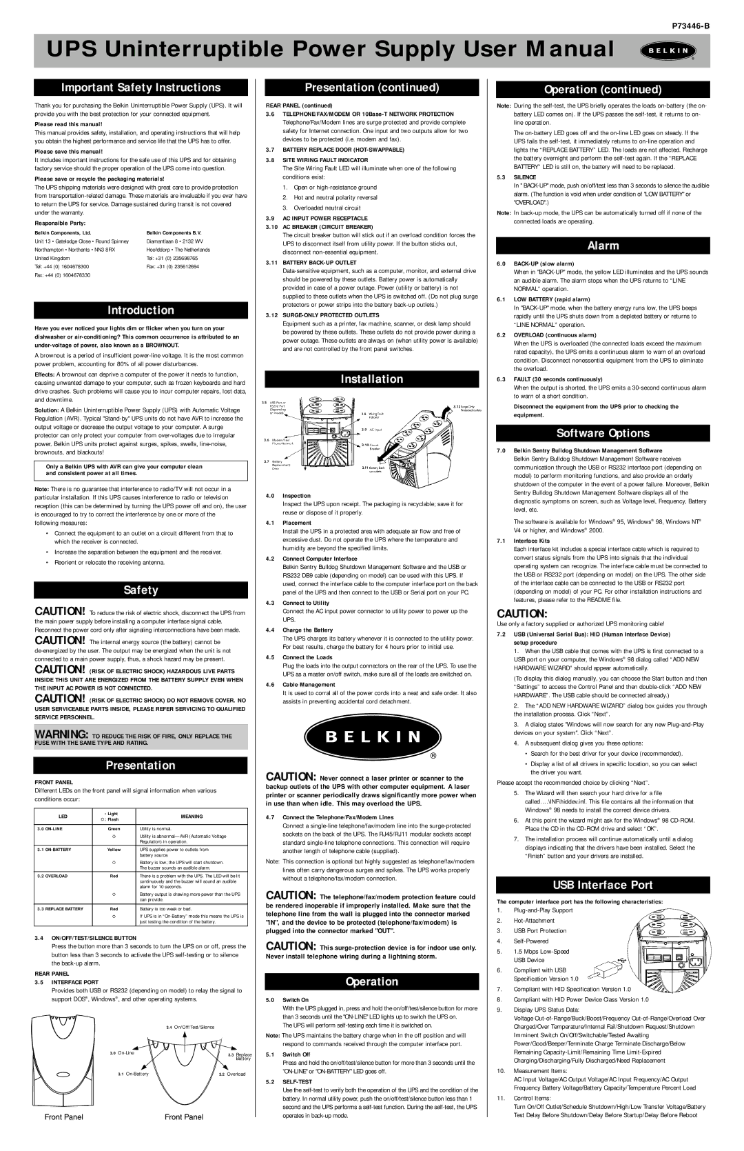
FRONT PANEL
Different LEDs on the front panel will signal information when various conditions occur:
| LED | ∀: Light | MEANING |
| ∀: Flash |
| | |
| | | |
3.0 | ON-LINE | Green | Utility is normal. |
| | ∀ | Utility is abnormal—AVR (Automatic Voltage |
| | | Regulation) in operation. |
3.1 | ON-BATTERY | Yellow | UPS supplies power to outlets from |
| | | battery source. |
| | ∀ | Battery is low; the UPS will start shutdown. |
| | | The buzzer sounds an audible alarm. |
3.2 | OVERLOAD | Red | There is a problem with the UPS. The LED will be lit |
| | | continuously and the buzzer will sound an audible |
| | | alarm for 10 seconds. |
| | ∀ | Battery output is drawing more power than the UPS |
| | | can provide. |
3.3 | REPLACE BATTERY | Red | Battery is too weak or bad. |
∀If UPS is in “On-Battery” mode this means the UPS is just testing the condition of the battery.
3.4ON/OFF/TEST/SILENCE BUTTON
Press the button more than 3 seconds to turn the UPS on or off, press the button less than 3 seconds to activate the UPS self-testing or to silence the back-up alarm.
REAR PANEL
3.5INTERFACE PORT
Provides both USB or RS232 (depending on model) to relay the signal to support DOS®, Windows®, and other operating systems.
3.4 | On/Off/Test/Silence |
3.0 On-Line | 3.3 Replace |
| Battery |
3.1 On-Battery | 3.2 Overload |
Presentation (continued)
REAR PANEL (continued)
3.6TELEPHONE/FAX/MODEM OR 10Base-T NETWORK PROTECTION Telephone/Fax/Modem lines are surge protected and provide complete safety for Internet connection. One input and two outputs allow for two devices to be protected (i.e. modem and fax).
3.7BATTERY REPLACE DOOR (HOT-SWAPPABLE)
3.8SITE WIRING FAULT INDICATOR
The Site Wiring Fault LED will illuminate when one of the following conditions exist:
1.Open or high-resistance ground
2.Hot and neutral polarity reversal
3.Overloaded neutral circuit
3.9AC INPUT POWER RECEPTACLE
3.10AC BREAKER (CIRCUIT BREAKER)
The circuit breaker button will stick out if an overload condition forces the UPS to disconnect itself from utility power. If the button sticks out, disconnect non-essential equipment.
3.11BATTERY BACK-UP OUTLET
Data-sensitive equipment, such as a computer, monitor, and external drive should be powered by these outlets. Battery power is automatically provided in case of a power outage. Power (utility or battery) is not supplied to these outlets when the UPS is switched off. (Do not plug surge protectors or power strips into the battery back-up outlets.)
3.12SURGE-ONLY PROTECTED OUTLETS
Equipment such as a printer, fax machine, scanner, or desk lamp should be powered by these outlets. These outlets do not provide power during a power outage. These outlets are always on (when utility power is available) and are not controlled by the front panel switches.
Installation
4.0Inspection
Inspect the UPS upon receipt. The packaging is recyclable; save it for reuse or dispose of it properly.
4.1Placement
Install the UPS in a protected area with adequate air flow and free of excessive dust. Do not operate the UPS where the temperature and humidity are beyond the specified limits.
4.2Connect Computer Interface
Belkin Sentry Bulldog Shutdown Management Software and the USB or RS232 DB9 cable (depending on model) can be used with this UPS. If used, connect the interface cable to the computer interface port on the back panel of the UPS and then connect to the USB or Serial port on your PC.
4.3Connect to Utility
Connect the AC input power connector to utility power to power up the UPS.
4.4Charge the Battery
The UPS charges its battery whenever it is connected to the utility power. For best results, charge the battery for 4 hours prior to initial use.
4.5Connect the Loads
Plug the loads into the output connectors on the rear of the UPS. To use the UPS as a master on/off switch, make sure all of the loads are switched on.
4.6Cable Management
It is used to corral all of the power cords into a neat and safe order. It also assists in preventing accidental cord detachment.
CAUTION: Never connect a laser printer or scanner to the backup outlets of the UPS with other computer equipment. A laser printer or scanner periodically draws significantly more power when in use than when idle. This may overload the UPS.
4.7Connect the Telephone/Fax/Modem Lines
Connect a single-line telephone/fax/modem line into the surge-protected sockets on the back of the UPS. The RJ45/RJ11 modular sockets accept standard single-line telephone connections. This connection will require another length of telephone cable (supplied).
Note: This connection is optional but highly suggested as telephone/fax/modem lines often carry dangerous surges and spikes. The UPS works properly without a telephone/fax/modem connection.
CAUTION: The telephone/fax/modem protection feature could be rendered inoperable if improperly installed. Make sure that the telephone line from the wall is plugged into the connector marked "IN", and the device to be protected (telephone/fax/modem) is plugged into the connector marked "OUT".
CAUTION: This surge-protection device is for indoor use only. Never install telephone wiring during a lightning storm.
Operation
5.0Switch On
With the UPS plugged in, press and hold the on/off/test/silence button for more than 3 seconds until the "ON-LINE" LED lights up to switch the UPS on.
The UPS will perform self-testing each time it is switched on.
Note: The UPS maintains the battery charge when in the off position and will respond to commands received through the computer interface port.
5.1Switch Off
Press and hold the on/off/test/silence button for more than 3 seconds until the "ON-LINE" or "ON-BATTERY" LED goes off.
5.2SELF-TEST
Use the self-test to verify both the operation of the UPS and the condition of the battery. In normal utility power, push the on/off/test/silence button less than 1 second and the UPS performs a self-test function. During the self-test, the UPS operates in back-up mode.
Operation (continued)
Note: During the self-test, the UPS briefly operates the loads on-battery (the on- battery LED comes on). If the UPS passes the self-test, it returns to on- line operation.
The on-battery LED goes off and the on-line LED goes on steady. If the UPS fails the self-test, it immediately returns to on-line operation and lights the “REPLACE BATTERY” LED. The loads are not affected. Recharge the battery overnight and perform the self-test again. If the “REPLACE BATTERY” LED is still on, the battery will need to be replaced.
5.3SILENCE
In " BACK-UP" mode, push on/off/test less than 3 seconds to silence the audible alarm. (The function is void when under condition of "LOW BATTERY" or "OVERLOAD".)
Note: In back-up mode, the UPS can be automatically turned off if none of the connected loads are operating.
Alarm
6.0BACK-UP (slow alarm)
When in "BACK-UP" mode, the yellow LED illuminates and the UPS sounds an audible alarm. The alarm stops when the UPS returns to “LINE NORMAL” operation.
6.1LOW BATTERY (rapid alarm)
In "BACK-UP" mode, when the battery energy runs low, the UPS beeps rapidly until the UPS shuts down from a depleted battery or returns to “LINE NORMAL” operation.
6.2OVERLOAD (continuous alarm)
When the UPS is overloaded (the connected loads exceed the maximum rated capacity), the UPS emits a continuous alarm to warn of an overload condition. Disconnect nonessential equipment from the UPS to eliminate the overload.
6.3FAULT (30 seconds continuously)
When the output is shorted, the UPS emits a 30-second continuous alarm to warn of a short condition.
Disconnect the equipment from the UPS prior to checking the equipment.
Software Options
7.0Belkin Sentry Bulldog Shutdown Management Software Belkin Sentry Bulldog Shutdown Management Software receives communication through the USB or RS232 interface port (depending on model) to perform monitoring functions, and also provide an orderly shutdown of the computer in the event of a power failure. Moreover, Belkin Sentry Bulldog Shutdown Management Software displays all of the diagnostic symptoms on screen, such as Voltage level, Frequency, Battery level, etc.
The software is available for Windows® 95, Windows® 98, Windows NT® V4 or higher, and Windows® 2000.
7.1Interface Kits
Each interface kit includes a special interface cable which is required to convert status signals from the UPS into signals that the individual operating system can recognize. The interface cable must be connected to the USB or RS232 port (depending on model) on the UPS. The other side of the interface cable can be connected to the USB or RS232 port (depending on model) of your PC. For other installation instructions and features, please refer to the README file.
CAUTION:
Use only a factory supplied or authorized UPS monitoring cable!
7.2USB (Universal Serial Bus): HID (Human Interface Device) setup procedure
1. When the USB cable that comes with the UPS is first connected to a USB port on your computer, the Windows® 98 dialog called “ADD NEW HARDWARE WIZARD” should appear automatically.
(To display this dialog manually, you can choose the Start button and then “Settings” to access the Control Panel and then double-click “ADD NEW HARDWARE”. The USB cable should be connected already.)
2.The “ADD NEW HARDWARE WIZARD” dialog box guides you through the installation process. Click “Next”.
3.A dialog states "Windows will now search for any new Plug-and-Play devices on your system". Click “Next”.
4.A subsequent dialog gives you these options:
•Search for the best driver for your device (recommended).
•Display a list of all drivers in specific location, so you can select the driver you want.
Please accept the recommended choice by clicking “Next”.
5.The Wizard will then search your hard drive for a file called….\INF\hiddev.inf. This file contains all the information that Windows® 98 needs to install the correct device drivers.
6.At this point the wizard might ask for the Windows® 98 CD-ROM. Place the CD in the CD-ROM drive and select “OK”.
7.The installation process will continue automatically until a dialog displays indicating that the drivers have been installed. Select the “Finish” button and your drivers are installed.
USB Interface Port
The computer interface port has the following characteristics:
1.Plug-and-Play Support
2.Hot-Attachment
3.USB Port Protection
4.Self-Powered
5.1.5 Mbps Low-Speed USB Device
6.Compliant with USB Specification Version 1.0
7.Compliant with HID Specification Version 1.0
8.Compliant with HID Power Device Class Version 1.0
9.Display UPS Status Data:
Voltage Out-of-Range/Buck/Boost/Frequency Out-of-Range/Overload Over Charged/Over Temperature/Internal Fail/Shutdown Request/Shutdown Imminent Switch On/Off/Switchable/Tested Awaiting Power/Good/Beeper/Terminate Charge Terminate Discharge/Below Remaining Capacity-Limit/Remaining Time Limit-Expired Charging/Discharging/Fully Discharged/Need Replacement
10.Measurement Items:
AC Input Voltage/AC Output Voltage/AC Input Frequency/AC Output Frequency Battery Voltage/Battery Capacity/Temperature Percent Load
11.Control Items:
Turn On/Off Outlet/Schedule Shutdown/High/Low Transfer Voltage/Battery Test Delay Before Shutdown/Delay Before Startup/Delay Before Reboot