feature allows the
When the
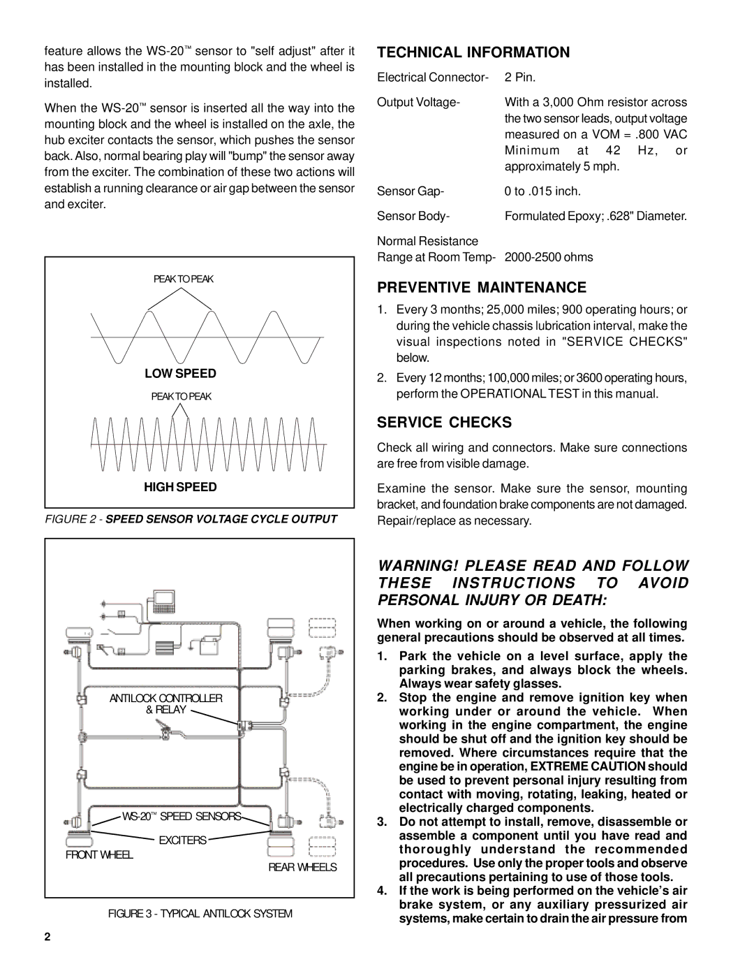
PEAK TO PEAK |
LOW SPEED |
PEAK TO PEAK |
HIGH SPEED |
FIGURE 2 - SPEED SENSOR VOLTAGE CYCLE OUTPUT
TECHNICAL INFORMATION
Electrical Connector- | 2 Pin. |
Output Voltage- | With a 3,000 Ohm resistor across |
| the two sensor leads, output voltage |
| measured on a VOM = .800 VAC |
| Minimum at 42 Hz, or |
| approximately 5 mph. |
Sensor Gap- | 0 to .015 inch. |
Sensor Body- | Formulated Epoxy; .628" Diameter. |
Normal Resistance |
|
Range at Room Temp- |
PREVENTIVE MAINTENANCE
1.Every 3 months; 25,000 miles; 900 operating hours; or during the vehicle chassis lubrication interval, make the visual inspections noted in "SERVICE CHECKS" below.
2.Every 12 months; 100,000 miles; or 3600 operating hours, perform the OPERATIONAL TEST in this manual.
SERVICE CHECKS
Check all wiring and connectors. Make sure connections are free from visible damage.
Examine the sensor. Make sure the sensor, mounting bracket, and foundation brake components are not damaged. Repair/replace as necessary.
ANTILOCK CONTROLLER
& RELAY
EXCITERS
FRONT WHEEL
REAR WHEELS
FIGURE 3 - TYPICAL ANTILOCK SYSTEM
WARNING! PLEASE READ AND FOLLOW THESE INSTRUCTIONS TO AVOID PERSONAL INJURY OR DEATH:
When working on or around a vehicle, the following general precautions should be observed at all times.
1.Park the vehicle on a level surface, apply the parking brakes, and always block the wheels. Always wear safety glasses.
2.Stop the engine and remove ignition key when working under or around the vehicle. When working in the engine compartment, the engine should be shut off and the ignition key should be removed. Where circumstances require that the engine be in operation, EXTREME CAUTION should be used to prevent personal injury resulting from contact with moving, rotating, leaking, heated or electrically charged components.
3.Do not attempt to install, remove, disassemble or assemble a component until you have read and thoroughly understand the recommended procedures. Use only the proper tools and observe all precautions pertaining to use of those tools.
4.If the work is being performed on the vehicle’s air brake system, or any auxiliary pressurized air systems, make certain to drain the air pressure from
2
