SPEED SENSOR | 100 TOOTH |
MOUNTING | |
BLOCK | EXCITER |
| MOUNTING |
| BLOCK |
| |
100 TOOTH SPEED | SENSOR |
| |
SENSOR EXCITER |
|
RING | BRAKE DRUM |
| |
| MAX. GAP |
| (SENSOR TO EXCITER) |
| .015 INCHES |
SENSOR (90 DEG.)
HUB ASSEMBLY
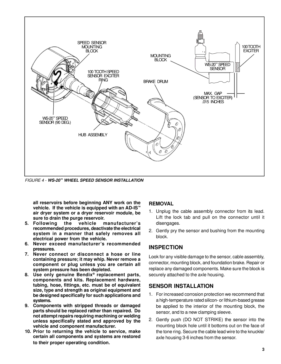
FIGURE 4 - WS-20™ WHEEL SPEED SENSOR INSTALLATION
all reservoirs before beginning ANY work on the vehicle. If the vehicle is equipped with an
5.Following the vehicle manufacturer’s recommended procedures, deactivate the electrical system in a manner that safely removes all electrical power from the vehicle.
6.Never exceed manufacturer’s recommended pressures.
7.Never connect or disconnect a hose or line containing pressure; it may whip. Never remove a component or plug unless you are certain all system pressure has been depleted.
8.Use only genuine Bendix® replacement parts, components and kits. Replacement hardware, tubing, hose, fittings, etc. must be of equivalent size, type and strength as original equipment and be designed specifically for such applications and systems.
9.Components with stripped threads or damaged parts should be replaced rather than repaired. Do not attempt repairs requiring machining or welding unless specifically stated and approved by the vehicle and component manufacturer.
10.Prior to returning the vehicle to service, make certain all components and systems are restored to their proper operating condition.
REMOVAL
1.Unplug the cable assembly connector from its lead. Lift the lock tab and pull on the connector until it disengages.
2.Gently pry the sensor and bushing from the mounting block.
INSPECTION
Look for any visible damage to the sensor, cable assembly, connector, mounting block, and foundation brake. Repair or replace any damaged components. Make sure the block is securely attached to the axle housing.
SENSOR INSTALLATION
1.For increased corrosion protection we recommend that a
2.Gently push (DO NOT STRIKE) the sensor into the mounting block hole until it bottoms out on the face of the tone ring. Secure the cable lead wire to the knuckle/ axle housing
3
