2. Side clearances (Minimum values)
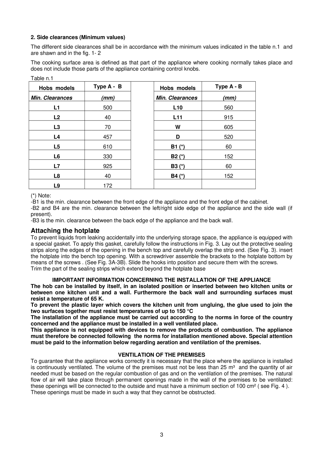
The different side clearances shall be in accordance with the minimum values indicated in the table n.1 and are shawn and in the fig. 1- 2
The cooking surface area is defined as that part of the appliance where cooking normally takes place and does not include those parts of the appliance containing control knobs.
Table n.1
Hobs models | Type A - B |
| Hobs models | Type A - B |
Min. Clearances | (mm) |
| Min. Clearances | (mm) |
L1 | 500 |
| L10 | 560 |
L2 | 40 |
| L11 | 915 |
L3 | 70 |
| W | 605 |
L4 | 457 |
| D | 520 |
L5 | 610 |
| B1 (*) | 60 |
L6 | 330 |
| B2 (*) | 152 |
L7 | 925 |
| B3 (*) | 60 |
L8 | 40 |
| B4 (*) | 152 |
L9 | 172 |
|
|
|
(*) Note:
Attaching the hotplate
To prevent liquids from leaking accidentally into the underlying storage space, the appliance is equipped with a special gasket. To apply this gasket, carefully follow the instructions in Fig. 3. Lay out the protective sealing strips along the edges of the opening in the bench top and carefully overlap the strip end. (See Fig. 3). insert the hotplate into the bench top opening. With a screwdriver assemble the brackets to the hotplate bottom by means of the screws . (See Fig.
Trim the part of the sealing strips which extend beyond the hotplate base
IMPORTANT INFORMATION CONCERNING THE INSTALLATION OF THE APPLIANCE
The hob can be installed by itself, in an isolated position or inserted between two kitchen units or between one kitchen unit and a wall. Furthermore the back wall and surrounding surfaces must resist a temperature of 65 K.
To prevent the plastic layer which covers the kitchen unit from ungluing, the glue used to join the two surfaces together must resist temperatures of up to 150 °C
The installation of the appliance must be carried out according to the norms in force of the country concerned and the appliance must be installed in a well ventilated place.
This appliance is not equipped with devices to remove the products of combustion. The appliance must therefore be connected following the norms for installation mentioned above. Special attention must be paid to the information below regarding aeration and ventilation of the premises.
VENTILATION OF THE PREMISES
To guarantee that the appliance works correctly it is necessary that the place where the appliance is installed is continuously ventilated. The volume of the premises must not be less than 25 m³ and the quantity of air needed must be based on the regular combustion of gas and on the ventilation of the premises. The natural flow of air will take place through permanent openings made in the wall of the premises to be ventilated: these openings will be connected to the outside and must have a minimum section of 100 cm² ( see Fig. 4 ).
These openings must be made in such a way that they cannot be obstructed.
3