WIRING
![]() !
! ![]() CAUTION: All electrical wiring should be done by a qualified person (s) in accordance with all applicable codes and standards. This range hood must be properly grounded.
CAUTION: All electrical wiring should be done by a qualified person (s) in accordance with all applicable codes and standards. This range hood must be properly grounded.
Do not turn power on at service panel until all wires have been connected.
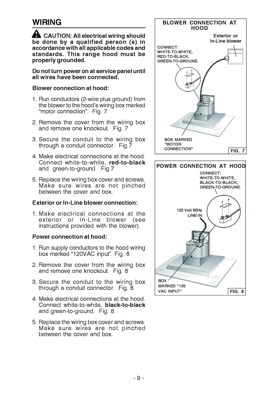
Blower connection at hood:
1.Run conductors
2.Remove the cover from the wiring box and remove one knockout. Fig. 7
3.Secure the conduit to the wiring box through a conduit connector. Fig.7
4.Make electrical connections at the hood. Connect
5.Replace the wiring box cover and screws. Make sure wires are not pinched between the cover and box.
Exterior or In-Line blower connection:
1.Make electrical connections at the exterior or
Power connection at hood:
1.Run supply conductors to the hood wiring box marked “120VAC input”. Fig. 8
2.Remove the cover from the wiring box and remove one knockout. Fig. 8
3.Secure the conduit to the wiring box through a conduit connector. Fig. 8
4.Make electrical connections at the hood. Connect
5.Replace the wiring box cover and screws. Make sure wires are not pinched between the cover and box.
BLOWER CONNECTION AT
HOOD
Exterior or
CONNECT:
BOX MARKED |
|
“MOTOR |
|
CONNECTION” | FIG. 7 |
|
POWER CONNECTION AT HOOD
CONNECT:
WHITE-TO-WHITE,
BLACK-TO-BLACK,
GREEN-TO-GROUND.
120 Volt 60Hz
LINE-IN
BOX |
|
MARKED “120 |
|
VAC INPUT” | FIG. 8 |
- 9 -