17 MAINTENANCE continued
Clear intake screens on housing and engine throughout use. Inspect machine for loose bolts before starting engine.
Lubrication: Using S.A.E. 30 weight oil or equivalent. See maintenance schedule. Chain: See SP section below.
Lower Control Ends: Oil moving parts, such as bail, and deflector door pivots.
Grease: Front wheel, and Caster(SP only).
Tire air pressure: Check at regular intervals & maintain: Low tire pressure will make unit hard to push and turn.
Front tire at 30 psi. (21.1 kPa).
Rear push 16" tires at 30 psi. (21.1 kPa). Rear SP 16" tires at 35 psi. (24.6 kPa).
Rear caster tire (SP only) at 30 psi (21.1 kPa)
17.3DRIVE
Chains and Belts are normal replaceable wear items. A new chain should not be used on worn sprockets. Sprockets should be inspected and replaced when worn.
MAINTENANCE- SP MODELS ONLY
Brake Adjustment: As parking brake wears, the brake discs may eventually require adjustment. To adjust, remove bottom guard from engine base and tighten brake adjusting nut on transmission. Adjust cable nut as required. Unit must free- wheel in neutral with clutch engaged and brake off.
DO NOT OVER ADJUST.
Chain Adjustment: (See fig. 11)
1.Remove spark plug wire.
2.Remove bottom drive guard.
3.Inspect chain and sprockets for wear, lubrication and tension. Replace if badly worn or damaged. Skip to CHAIN
REPLACEMENT
4.Check chain tension. There should be no more than 0.25" total movement when chain is flexed from top to bottom.
5.To increase chain tension, loosen, do not remove, the bolts that hold the bearings in place on each side and in the center of the differential.
6.Loosen, do not remove, the Jam nut that locks the bolt into the chain tensioner on each side of the differential.
7.With the bolts loose, equally tighten the chain tensioner bolt on both the left and right side of the differential.
8.Adjust in small increments, checking chain alignment, tension and axle squareness between steps. Roll wheels to check that there are no excessively tight areas in the chain. Repeat adjustment steps if necessary. A slightly loose chain is better than an over tightened one.
9.With chain properly adjusted securely tighten the jam nuts, and bearing mount bolts.
10.Reinstall drive guard.
11.Reconnect spark plug wire.
Chain Lubrication: With machine not running, oil chain using general purpose S.A.E. 30 weight oil every 25 hours or as needed. Chain oiling hole is located on operator's left at rear of engine base. Note: Be sure that entire length of chain is properly oiled. Oiling only a few positions in the chain rotation will not properly oil the chain.
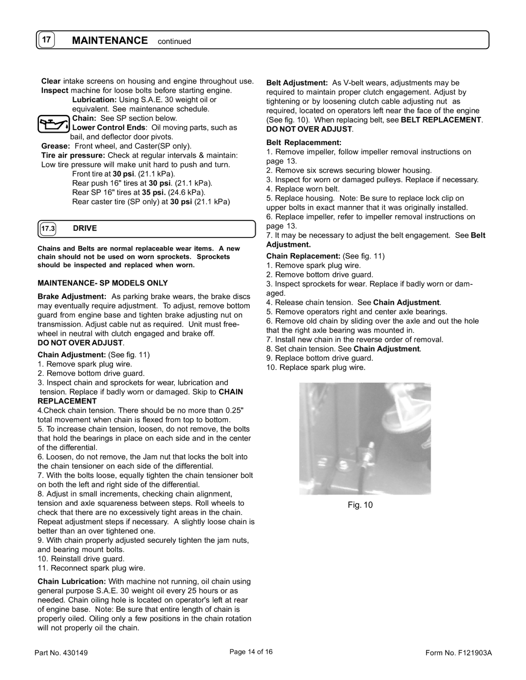
Belt Adjustment: As
DO NOT OVER ADJUST.
Belt Replacemment:
1.Remove impeller, follow impeller removal instructions on page 13.
2.Remove six screws securing blower housing.
3.Inspect for worn or damaged pulleys. Replace if necessary.
4.Replace worn belt.
5.Replace housing. Note: Be sure to replace lock clip on upper bolts in exact manner that it was originally installed.
6.Replace impeller, refer to impeller removal instructions on page 13.
7.It may be necessary to adjust the belt engagement. See Belt Adjustment.
Chain Replacement: (See fig. 11)
1.Remove spark plug wire.
2.Remove bottom drive guard.
3.Inspect sprockets for wear. Replace if badly worn or dam- aged.
4.Release chain tension. See Chain Adjustment.
5.Remove operators right and center axle bearings.
6.Remove old chain by sliding over the axle and out the hole that the right axle bearing was mounted in.
7.Install new chain in the reverse order of removal.
8.Set chain tension. See Chain Adjustment.
9.Replace bottom drive guard.
10.Replace spark plug wire.
Fig. 10
Part No. 430149 | Page 14 of 16 | Form No. F121903A |
