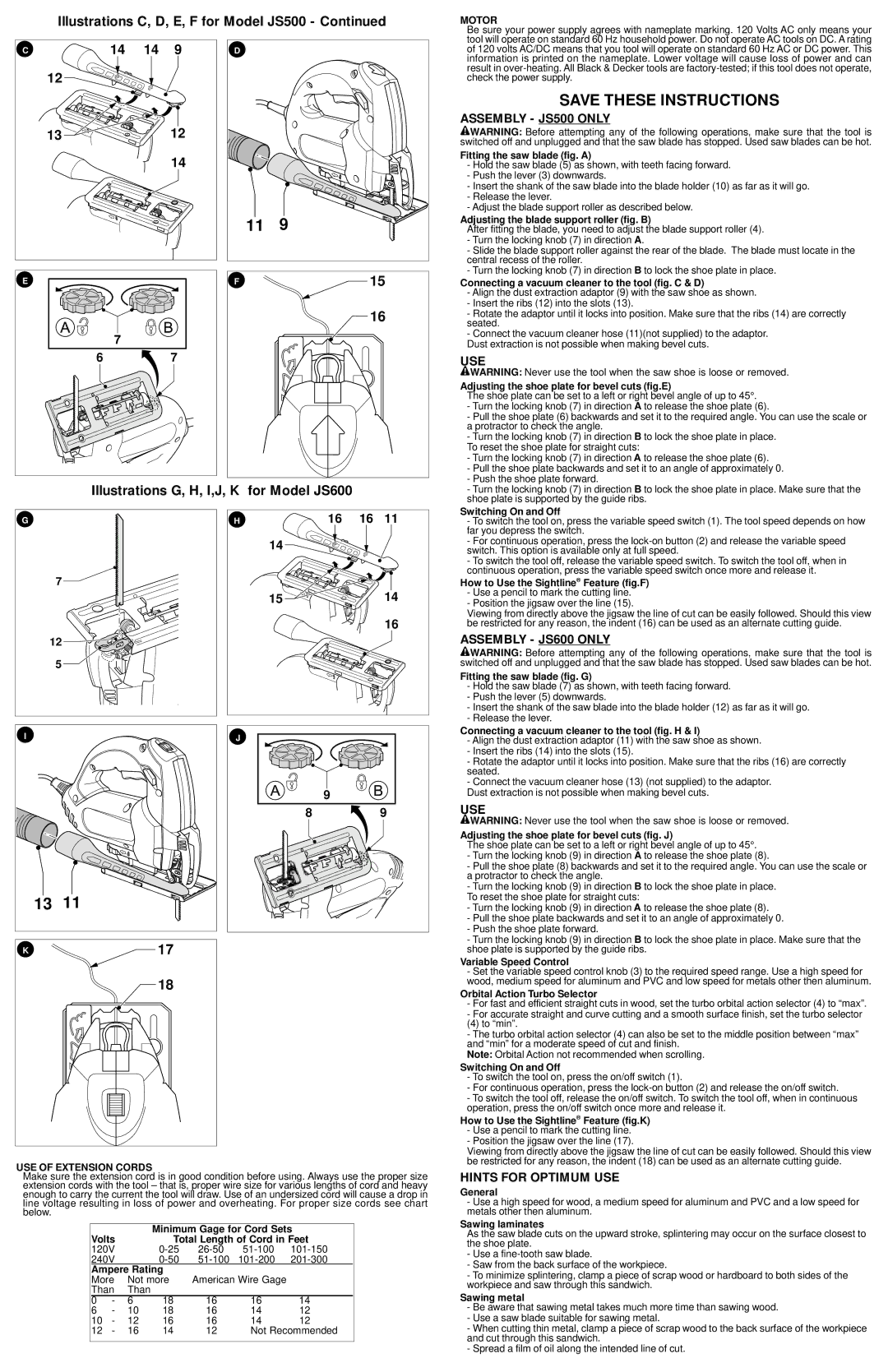
Illustrations C, D, E, F for Model JS500 - Continued
MOTOR
C | 14 14 9 |
12
13
![]()
![]() 12
12
14
E |
|
| 7 |
6 | 7 |
D |
|
11 | 9 |
F | 15 |
| 16 |
Be sure your power supply agrees with nameplate marking. 120 Volts AC only means your tool will operate on standard 60 Hz household power. Do not operate AC tools on DC. A rating of 120 volts AC/DC means that you tool will operate on standard 60 Hz AC or DC power. This information is printed on the nameplate. Lower voltage will cause loss of power and can result in
SAVE THESE INSTRUCTIONS
ASSEMBLY - JS500 ONLY
![]() WARNING: Before attempting any of the following operations, make sure that the tool is switched off and unplugged and that the saw blade has stopped. Used saw blades can be hot.
WARNING: Before attempting any of the following operations, make sure that the tool is switched off and unplugged and that the saw blade has stopped. Used saw blades can be hot.
Fitting the saw blade (fig. A)
-Hold the saw blade (5) as shown, with teeth facing forward.
-Push the lever (3) downwards.
-Insert the shank of the saw blade into the blade holder (10) as far as it will go.
-Release the lever.
-Adjust the blade support roller as described below.
Adjusting the blade support roller (fig. B)
After fitting the blade, you need to adjust the blade support roller (4).
-Turn the locking knob (7) in direction A.
-Slide the blade support roller against the rear of the blade. The blade must locate in the central recess of the roller.
-Turn the locking knob (7) in direction B to lock the shoe plate in place.
Connecting a vacuum cleaner to the tool (fig. C & D)
-Align the dust extraction adaptor (9) with the saw shoe as shown.
-Insert the ribs (12) into the slots (13).
-Rotate the adaptor until it locks into position. Make sure that the ribs (14) are correctly seated.
-Connect the vacuum cleaner hose (11)(not supplied) to the adaptor.
Dust extraction is not possible when making bevel cuts.
USE
![]() WARNING: Never use the tool when the saw shoe is loose or removed.
WARNING: Never use the tool when the saw shoe is loose or removed.
Adjusting the shoe plate for bevel cuts (fig.E)
The shoe plate can be set to a left or right bevel angle of up to 45°.
-Turn the locking knob (7) in direction A to release the shoe plate (6).
-Pull the shoe plate (6) backwards and set it to the required angle. You can use the scale or a protractor to check the angle.
-Turn the locking knob (7) in direction B to lock the shoe plate in place.
To reset the shoe plate for straight cuts:
Illustrations G, H, I,J, K for Model JS600
-Turn the locking knob (7) in direction A to release the shoe plate (6).
-Pull the shoe plate backwards and set it to an angle of approximately 0.
-Push the shoe plate forward.
-Turn the locking knob (7) in direction B to lock the shoe plate in place. Make sure that the shoe plate is supported by the guide ribs.
G |
|
7 |
|
12 |
|
5 |
|
I |
|
13 | 11 |
K | 17 |
| 18 |
H | 16 16 11 |
14
15 | 14 |
| 16 |
J |
|
| 9 |
8 | 9 |
Switching On and Off
-To switch the tool on, press the variable speed switch (1). The tool speed depends on how far you depress the switch.
-For continuous operation, press the
-To switch the tool off, release the variable speed switch. To switch the tool off, when in continuous operation, press the variable speed switch once more and release it.
How to Use the Sightline® Feature (fig.F)
-Use a pencil to mark the cutting line.
-Position the jigsaw over the line (15).
Viewing from directly above the jigsaw the line of cut can be easily followed. Should this view be restricted for any reason, the indent (16) can be used as an alternate cutting guide.
ASSEMBLY - JS600 ONLY
![]() WARNING: Before attempting any of the following operations, make sure that the tool is switched off and unplugged and that the saw blade has stopped. Used saw blades can be hot.
WARNING: Before attempting any of the following operations, make sure that the tool is switched off and unplugged and that the saw blade has stopped. Used saw blades can be hot.
Fitting the saw blade (fig. G)
-Hold the saw blade (7) as shown, with teeth facing forward.
-Push the lever (5) downwards.
-Insert the shank of the saw blade into the blade holder (12) as far as it will go.
-Release the lever.
Connecting a vacuum cleaner to the tool (fig. H & I)
-Align the dust extraction adaptor (11) with the saw shoe as shown.
-Insert the ribs (14) into the slots (15).
-Rotate the adaptor until it locks into position. Make sure that the ribs (16) are correctly seated.
-Connect the vacuum cleaner hose (13) (not supplied) to the adaptor.
Dust extraction is not possible when making bevel cuts.
USE
![]() WARNING: Never use the tool when the saw shoe is loose or removed.
WARNING: Never use the tool when the saw shoe is loose or removed.
Adjusting the shoe plate for bevel cuts (fig. J)
The shoe plate can be set to a left or right bevel angle of up to 45°.
-Turn the locking knob (9) in direction A to release the shoe plate (8).
-Pull the shoe plate (8) backwards and set it to the required angle. You can use the scale or a protractor to check the angle.
-Turn the locking knob (9) in direction B to lock the shoe plate in place.
To reset the shoe plate for straight cuts:
-Turn the locking knob (9) in direction A to release the shoe plate (8).
-Pull the shoe plate backwards and set it to an angle of approximately 0.
-Push the shoe plate forward.
-Turn the locking knob (9) in direction B to lock the shoe plate in place. Make sure that the shoe plate is supported by the guide ribs.
Variable Speed Control
-Set the variable speed control knob (3) to the required speed range. Use a high speed for wood, medium speed for aluminum and PVC and low speed for metals other then aluminum.
Orbital Action Turbo Selector
-For fast and efficient straight cuts in wood, set the turbo orbital action selector (4) to “max”.
-For accurate straight and curve cutting and a smooth surface finish, set the turbo selector
(4) to “min”.
-The turbo orbital action selector (4) can also be set to the middle position between “max” and “min” for a moderate speed of cut and finish.
Note: Orbital Action not recommended when scrolling.
Switching On and Off
-To switch the tool on, press the on/off switch (1).
-For continuous operation, press the
-To switch the tool off, release the on/off switch. To switch the tool off, when in continuous operation, press the on/off switch once more and release it.
How to Use the Sightline® Feature (fig.K)
-Use a pencil to mark the cutting line.
-Position the jigsaw over the line (17).
USE OF EXTENSION CORDS
Make sure the extension cord is in good condition before using. Always use the proper size extension cords with the tool – that is, proper wire size for various lengths of cord and heavy enough to carry the current the tool will draw. Use of an undersized cord will cause a drop in line voltage resulting in loss of power and overheating. For proper size cords see chart below.
|
|
| Minimum Gage for Cord Sets | |||
Volts |
| Total Length of Cord in Feet | ||||
120V |
| |||||
240V |
| |||||
Ampere Rating |
|
|
| |||
More | Not more | American Wire Gage |
| |||
Than | Than |
|
|
|
| |
0 | - | 6 | 18 | 16 | 16 | 14 |
6 | - | 10 | 18 | 16 | 14 | 12 |
10 | - | 12 | 16 | 16 | 14 | 12 |
12 | - | 16 | 14 | 12 | Not Recommended | |
|
|
|
|
|
|
|
Viewing from directly above the jigsaw the line of cut can be easily followed. Should this view be restricted for any reason, the indent (18) can be used as an alternate cutting guide.
HINTS FOR OPTIMUM USE
General
-Use a high speed for wood, a medium speed for aluminum and PVC and a low speed for metals other then aluminum.
Sawing laminates
As the saw blade cuts on the upward stroke, splintering may occur on the surface closest to the shoe plate.
-Use a
-Saw from the back surface of the workpiece.
-To minimize splintering, clamp a piece of scrap wood or hardboard to both sides of the workpiece and saw through this sandwich.
Sawing metal
-Be aware that sawing metal takes much more time than sawing wood.
-Use a saw blade suitable for sawing metal.
-When cutting thin metal, clamp a piece of scrap wood to the back surface of the workpiece and cut through this sandwich.
-Spread a film of oil along the intended line of cut.