ASSEMBLY INSTRUCTIONS
BEFORE ASSEMBLING YOUR EDGER, CHECK THAT YOU HAVE RECEIVED THE FOLLOWING IN THE SHIPPING CARTON.
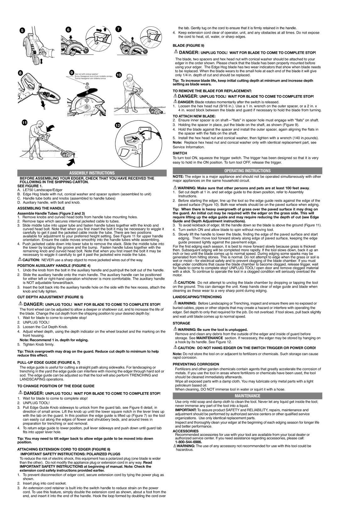
SEE FIGURE 1.
A.LE750 Landscape/Edger
B.Edge Hog blade with nut, conical washer and spacer system (assembled to unit)
C.Handle tube bolts and knobs (assembled to handle tubes)
D.Auxiliary handle, with bolt and knob.
ASSEMBLING THE HANDLE
Assemble Handle Tubes (Figure 2 and 3)
1.Remove knobs and curved head bolts from handle tube mounting holes.
2.Remove tape which secures internal jacketed cable to tubes.
3.Slide middle tube into upper tube and fasten handle tubes together with the knob and curved head bolt. Note that when you first insert the bolt it may be necessary to wiggle it carefully to get it past the jacketed cable inside the tube. There are two positions available for adjustment to your preferred height setting. See Figure 11 for upper handle orientation. Ensure the cable moves smoothly into the handle tubes while assembling.
4.Push jacketed cable down into lower tube to remove the slack. Slide the middle tube into the lower by locating the groove and the bump. Fasten handle tubes together with the remaining knob and curved head bolt. Note that when you first insert the bolt it may be necessary to wiggle it carefully to get it past the jacketed wire inside the tube.
 CAUTION: NEVER use a sharp object to move jacketed wires out of the way.
POSITION AUXILIARY HANDLE (FIGURE 4)
1.Undo the knob from the bolt in the auxiliary handle and push/pull the bolt out of the handle.
2.Slide the auxiliary handle onto the main handle. The auxiliary handle can be positioned for either left or right-hand operation whichever is more comfortable. The auxiliary handle is NOT adjustable forward/back.
3.Insert the bolt back into the auxiliary handle hole on the side with the hex recess, attach the knob and fully tighten.
CUT DEPTH ADJUSTMENT (FIGURE 5)
 DANGER: UNPLUG TOOL! WAIT FOR BLADE TO COME TO COMPLETE STOP!
The front wheel can be adjusted to allow a deeper or shallower cut, and to increase the life of the blade. Change the cut depth from the shipping position to your desired depth by:
1.Wait for blade to come to complete stop!
2.UNPLUG TOOL!
3.Loosen the Cut Depth Knob.
4.Adjust wheel depth, using the depth indicator on the wheel bracket and the marking on the front housing.
Note: Recommend 1 in. depth for edging.
5. Tighten Knob firmly.
Tip: Thick overgrowth may drag on the guard. Reduce cut depth to minimum to help reduce this effect.
PULL-UP EDGE GUIDE (FIGURE 6, 7)
The edge guide is useful for cutting a straight path along sidewalks. For landscaping or trenching in the yard the edge guide can interfere with moving the edger through hard soil or sod. The edge guide can be adjusted so that the tool will also perform TRENCHING and LANDSCAPING operations.
TO CHANGE POSITION OF THE EDGE GUIDE
 DANGER: UNPLUG TOOL! WAIT FOR BLADE TO COME TO COMPLETE STOP!
1.Wait for blade to come to complete stop!
2.UNPLUG TOOL!
3.Pull Edge Guide Knob sideways to unlock from the guard tab, see Figure 6 detail, in direction of small arrow. Lift the knob up until the lower square notch in the lever lines up with the tab on the guard. In this position the edge guide is lifted up (Figure 7) so the tool can easily cut along the edges of flower and shrubbery beds, and around trees in preparation for trenching or sod removal.
4.To return edge guide to lower position, pull lever sideways and push down until guard tab fits into upper lever hole.
Tip: You may need to tilt edger back to allow edge guide to be moved into down position.
ATTACHING EXTENSION CORD TO EDGER (FIGURE 8)
IMPORTANT SAFETY INSTRUCTIONS: POLARIZED PLUGS
To reduce the risk of electric shock, this equipment has a polarized plug (one blade is wider than the other). Do not modify the appliance plug or extension cord in any way. Read
IMPORTANT SAFETY INSTRUCTIONS at beginning of manual. Note: Check the extension cord safety instructions provided earlier.
1.To prevent disconnection of edger cord, secure extension cord by tying the power plug as shown.
2.Insert plug into cord socket.
3.An extension cord retainer is built into the switch handle to reduce strain on the power cord. To use this feature, simply double the extension cord as shown, about a foot from the end, and insert it into the end of the handle. Hook the loop formed by doubling the cord over
OPERATING INSTRUCTIONS
NOTE: The edger is a major appliance and should not be operated simultaneously with other major appliances on the same household circuit.
 WARNING: Make sure that other persons and pets are at least 100 feet away.
1.Set cut depth at 1 in. and set edge guide to the down position, refer to Assembly Instructions.
2.Before starting the edger, line up the tool so the edge guide rests against the edge of the paved surface (Figure 10). Both rear wheels should be on the paved surface when edging.
Tip: When there is heavy overgrowth of grass over the paved surface it may drag on the guard. An initial cut may be required with the edger on the grass side. This will require lifting up the edge guide and may require reducing the depth of cut (see Edge Guide and Depth Adjustment instructions).
3.To avoid kickback of edger, tilt the handle down so the blade is above the ground (Figure 11).
4.Turn switch ON and allow blade to spin without moving tool.
5.Slowly lift the handle to lower the blade, finding the edge of the paved surface and start edging. Then move tool forward slowly along edge of paved surface, keeping the edge guide pressed lightly against the pavement edge.
For the first edging each season, it is best to move forward slowly because grass is thickest then. Subsequent edging will be completed more rapidly. If the tool slows down, back it up an inch or two until the blade comes up to normal speed. During edging some sparks may be generated from hitting stones. This is normal. Do not attempt to edge when the grass or soil is wet or moist—for electrical safety and to prevent clogging of the blade chamber. If you must edge under conditions that cause the blade chamber to become clogged, release trigger, wait for blade to come to complete stop! UNPLUG TOOL! open door and remove clogged material with a stick. To continue to operate the tool in a clogged condition will seriously overload the motor.
 CAUTION: Do not attempt to unclog the blade chamber by dropping or tapping the tool on the ground. This can damage the unit. Keep hands clear of edge guide and blade when cleaning as these wear to a very sharp point during edging.
LANDSCAPING/TRENCHING
 WARNING: Before Landscaping or Trenching, inspect and ensure there are no exposed or buried cables, pipes or other objects that may create a hazard or interfere with operating the edger. Set depth to only that required for the job. Do not overload. If tool slows, pull back slightly and wait until blade comes up to normal speed.
STORAGE
 WARNING: Be sure the tool is unplugged.
Remove and clean any debris from the outside of the edger and inside of guard before storage. See MAINTENANCE section. If necessary, the edger may be stored by hanging on a hook by its handle. See Figure 12.
 CAUTION: DO NOT HANG EDGER ON THE SWITCH TRIGGER OR POWER CORD!
Note: Do not store the tool on or adjacent to fertilizers or chemicals. Such storage can cause rapid corrosion.
PREVENTING CORROSION
Fertilizers and other garden chemicals contain agents that greatly accelerate the corrosion of metals. If you use the tool in areas where fertilizers or chemicals have been used, the tool should be cleaned immediately afterwards.
Wipe all exposed parts with a damp cloth. You may lubricate only metal parts with a light petroleum based oil.
When cleaning, DO NOT immerse tool in water or squirt it with a hose.
MAINTENANCE
Use only mild soap and damp cloth to clean the tool. Never let any liquid get inside the tool; never immerse any part of the tool into a liquid.
IMPORTANT: To assure product SAFETY and RELIABILITY, repairs, maintenance and adjustment should be performed by authorized service centers or other qualified service organizations. Use only identical replacement parts.
Inspect and thoroughly clean your edger at the beginning of each edging season for longer life and better performance.
ACCESSORIES
Recommended accessories for use with your tool are available from your local dealer or authorized service center. If you need assistance regarding accessories, please call:
1-800-544-6986.
 WARNING: The use of any accessory not recommended for use with this tool could be hazardous.