HD View – NEC-Integrated Receivers
Installation Steps
1.Turn the display off completely, using the hard on/off switch, or disconnect the equipment fully from the main power supply.
2.The receiver must be placed in the
3.Remove the carrying handle by loosening the two
4.Remove the cover panel over the
5.Ensure that the receiver is inserted wtih the right orientation. Orientation is correct when the tuning port is on top and the connector labeling is not upside down.
6.Use the screws that previously held the cover panel in place to secure the receiver.
7.
8.Connect the CATx cables between the system ports of the Broadcaster and the Receivers.
Operating and Maintenance
1.Understanding LEDs: The table below explains the functions of the LEDs of the units in the system. There are very short interruptions that can be observed in the “On“ state of the LED caused by presence scanning that the Transmitter performs.
Unit | LED | Function |
|
|
|
Transmitter/Broadcaster | Front Panel – Green | Power Indicator |
|
|
|
|
| Green – Power Indicator |
Rear Panel – | Yellow solid – Unit is connected to the system | |
| ||
|
| Yellow blinking – |
|
| using one receiver at a time) |
|
|
|
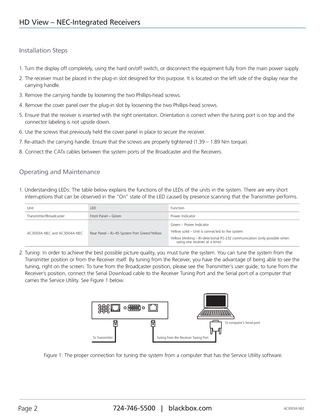
2.Tuning: In order to achieve the best possible picture quality, you must tune the system. You can tune the system from the Transmitter position or from the Receiver itself. By tuning from the Receiver, you have the advantage of being able to see the tuning, right on the screen. To tune from the Broadcaster position, please see the Transmitter‘s user guide; to tune from the Receiver‘s position, connect the Serial Download cable to the Receiver Tuning Port and the Serial port of a computer that carries the Service Utility. See Figure 1 below.
To Transmitter
To computer‘s Serial port
Tuning from the Receiver Tuning Port
Figure 1: The proper connection for tuning the system from a computer that has the Service Utility software.
Page 2 |