Trademarks Used in this Manual
Black Box and the Double Diamond logo, GigaBase2, and GigaTrue2 are registered trademarks of BB Technologies, Inc.
Any other trademarks mentioned in this manual are acknowledged to be the property of the trademark owners.
Assembly Instructions
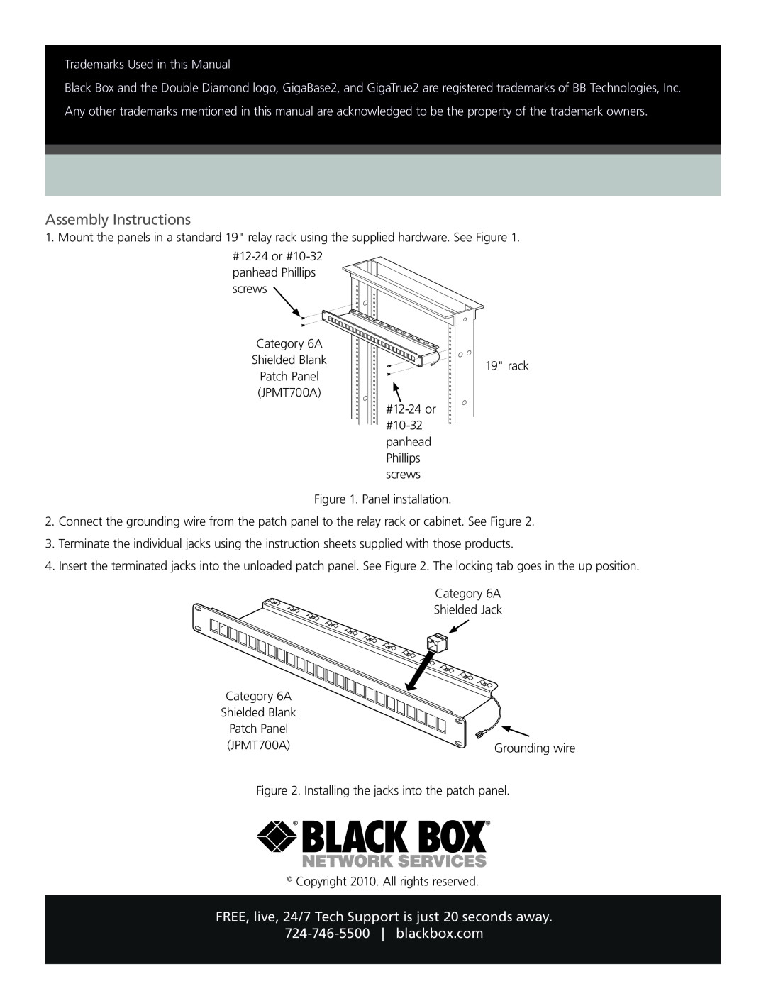
1. Mount the panels in a standard 19" relay rack using the supplied hardware. See Figure 1.
![]()
Category 6A
Shielded Blank
Patch Panel (JPMT700A)
19" rack
Figure 1. Panel installation.
2.Connect the grounding wire from the patch panel to the relay rack or cabinet. See Figure 2.
3.Terminate the individual jacks using the instruction sheets supplied with those products.
4.Insert the terminated jacks into the unloaded patch panel. See Figure 2. The locking tab goes in the up position.
Category 6A
Shielded Jack
Category 6A |
|
Shielded Blank |
|
Patch Panel |
|
(JPMT700A) | Grounding wire |
Figure 2. Installing the jacks into the patch panel.
© Copyright 2010. All rights reserved.