OPERATION
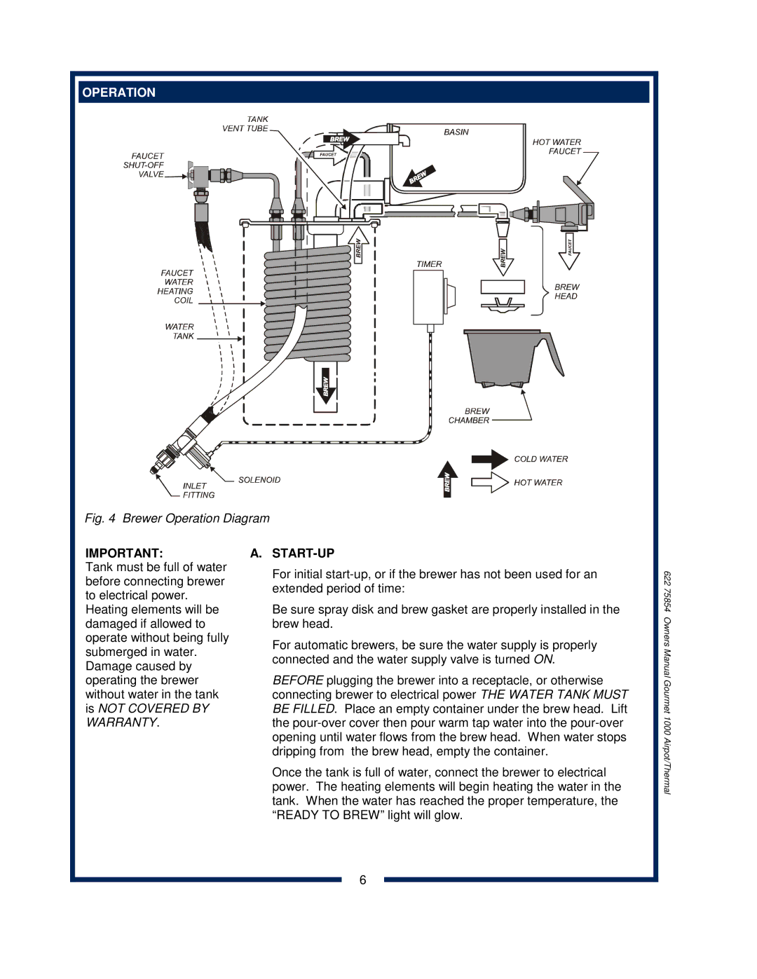
Fig. 4 Brewer Operation Diagram
IMPORTANT:
Tank must be full of water before connecting brewer to electrical power.
Heating elements will be damaged if allowed to operate without being fully submerged in water. Damage caused by operating the brewer without water in the tank is NOT COVERED BY WARRANTY.
A.START-UP
For initial
Be sure spray disk and brew gasket are properly installed in the brew head.
For automatic brewers, be sure the water supply is properly connected and the water supply valve is turned ON.
BEFORE plugging the brewer into a receptacle, or otherwise connecting brewer to electrical power THE WATER TANK MUST BE FILLED. Place an empty container under the brew head. Lift the
Once the tank is full of water, connect the brewer to electrical power. The heating elements will begin heating the water in the tank. When the water has reached the proper temperature, the “READY TO BREW” light will glow.
622 75854 Owners Manual Gourmet 1000 Airpot/Thermal
6