Fig. 23
Stroller with handle folded
AFOD correctly attached
Fig. 17
Cross Tube Wrist Strap
Brake pads shown aligned to rim
AFOD
Fig.16
Brake Pad
Nut
Clearance between brake pad & rim
10mm Caliper
Mounting Nut
Fig. 15
Brake
Pad
3/16” (5mm)
Brake
Body
Tire
Rim

DUALLIE OWNER’S MANUAL

with or without the parking brake set! After installing the

front wheel, the brake caliper will

need to be placed

in the closed position. Close the brake quick release (Fig. 10) by

squeezing the brake pads against

the wheel with one hand, then rotate

the brake quick

release lever in the counter clockwise

direction with your other hand until it points downward. To set the parking

brake, squeeze the brake lever and

press and hold the button down, then

release lever (Fig.

13 &14). When the brake is properly

set, the button will

remain depressed and the lever will

appear as shown

in Fig. 14. To release the parking

brake, simply

squeeze the brake lever and the button will “pop” up. For the parking brake to work correctly, it is critical that the brake be adjusted properly. Squeeze the brake lever and verify that the brake pads contact the rim as shown in Fig. 16. If they are misaligned, use a 10mm wrench to loosen brake pad nuts, slide pads into correct position and tighten securely. The cable tension is pre-adjusted at the factory yet the brake cable will need periodic adjustment (as the cable stretches slightly and the black cable housing compresses over time). To adjust cable tension, there are two barrel adjusters in the brake assembly (Fig. 10 &13). To tighten the cable, loosen the lock ring and turn the barrel adjuster in the counter clockwise direction. Secure the barrel adjuster in the new position by tightening the lock ring against the caliper or brake lever body. There should be a 3/16”(5mm) clearance between the rim and brake pads as shown in Fig. 15. If gap is not equal on each brake pad, you can reposition the brake on the frame by loosening the 10 mm nut (Fig. 16) with a 10mm wrench, adjust to the gap shown in Fig. 15 and retighten the same nut. If you do not understand these instructions, or feel the brake is adjusted incorrectly, take the stroller to your dealer for proper adjustment. If your brake pads (Fig. 10) are worn, see your dealer for replacements.

9. SUN CANOPY: The Duallie


Shoulder

features an independantly

Strap

adjustable two position sun


canopy for each seat. To fully


open a canopy, rotate the


assembly forward until the fabric


is taut. The rear canopy flap


should be freed from the Velcro


to give additional sun protection.


To reduce the size of a sun


canopy, pull the canopy toward


the handlebar. The additional


Fig. 19 Securely adjust shoulder straps

fabric can be gathered by pulling


the canopy drawstring (Fig. 1) and


securing the cord lock.

Sternum


Strap

10.SEAT TENSIONING: The seat compartments are divided by a section of nylon webbing that runs the length of the stroller. From time to time it may be necessary to increase the tension of the webbing. To adjust the tension start with handlebar in the fully

open position as shown in Fig 3. Fig. 20 Connect Sternum Strap At the top center of the seat the

webbing loops over the handlebar

Seat Reclining

cross tube and connects to a

Ladder Locks

ladderlock buckle. Under the


ladderlock buckle there is a


tensioning strap. Pull on this strap


to increase the tension.


11. SEAT SAFETY HARNESS:


Set parking brake before placing


child in stroller. To secure your

Fig. 21

child in the seat, put one shoulder


strap over each shoulder and snap

Reclining

the male buckle into the female

Strap Loops

receiver on the crotch strap (Fig.


18). Adjust shoulder straps to be


snug and secure (Fig. 19).


Connect and adjust the sternum


strap (red), see Fig. 20.


WARNING: Never place


passengers in the stroller without


securing them in the harness.

Fig.22 Seat in fully reclined position.

Unrestrained passengers can


affect the control of the stroller.

Passenger weight limit - 50 lbs (22.5 kg) per seat. Passenger height limit - 44 in. (112 cm)

12.RECLINING SEAT: Set parking brake before making any seat adjustments. To recline the seat,

rotate the ladder lock buckles

8.AFOD: With the stroller in the fully open position (Fig. 1), attach the AFOD (Anti-Fly-Out-Device) around the cross tube with the plastic buckle (Fig. 17). It is important that the AFOD is always properly secured when using the stroller, as it is part of the child’s seat restraint system. It is, however, necessary to release the AFOD in order to fold the stroller.

Shoulder

Strap

Crotch

Strap

Buckle

Fig. 18 Place straps over shoulders

and secure to buckle.

(Fig. 21) forward thus releasing the reclining straps. To raise the seat, pull the reclining strap loops until you obtain the desired position. The seat back can be adjusted to recline anywhere between

the fully upright position and the fully reclined position (Fig. 21 & 22).

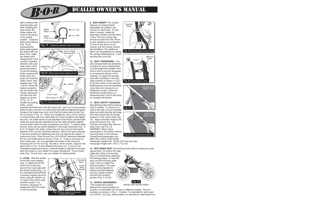
13. SHOCK ABSORBERS: The suspension system

features two shock positions to

provide a comfortable ride for kids of different weights. The two positions are shown in Fig. 2. Position 1 is intended for total loads up to 50 lbs. (22.5 kg), while position 2 is intended for total loads from

Page 3
Image 3
BOB MA0501A operating instructions SUN Canopy The Duallie, Seat Safety Harness, Shock Absorbers The suspension system

MA0501A specifications

The BOB MA0501A is a cutting-edge electronic module designed for modern applications in various fields, including robotics, automation, and IoT (Internet of Things). This versatile device is equipped with an array of features, technologies, and characteristics that make it an invaluable component for developers and engineers.

One of the standout aspects of the BOB MA0501A is its compact design. Measuring only a few centimeters in size, it allows for easy integration into limited spaces without compromising performance. This small footprint makes it ideal for applications where space is at a premium, such as wearable devices and compact robotic systems.

The BOB MA0501A comes with a powerful microcontroller that supports a wide range of programming languages, enhancing accessibility for developers with varied skill sets. The onboard microcontroller typically operates at speeds exceeding 16 MHz, ensuring efficient processing capabilities necessary for real-time applications. Furthermore, it supports various communication protocols, including UART, I2C, and SPI, enabling seamless connectivity with other devices.

Another important feature of the BOB MA0501A is its extensive range of input and output pins. This flexibility allows users to connect numerous sensors, actuators, and additional components, expanding the module's capabilities for diverse applications. The digital input/output pins can handle multiple voltage levels, accommodating different electronic components.

In terms of power efficiency, the BOB MA0501A is designed to operate within a wide voltage range, typically from 3.3V to 5V. This adaptability makes it compatible with standard battery systems, as well as power supplies commonly found in various electronic projects.

The BOB MA0501A also incorporates advanced security and data protection features. This is particularly important for IoT applications, where data integrity and protection against unauthorized access are critical concerns. Built-in encryption functionalities help safeguard sensitive information during data transmission.

Additionally, the BOB MA0501A is designed with modularity in mind, allowing for easy upgrades and modifications. This characteristic ensures that developers can adapt their projects to evolving technological needs without requiring a complete redesign. The combination of its robustness, functionality, and ease of use positions the BOB MA0501A as an excellent choice for both hobbyists and professionals looking to innovate in their projects.