Brake
Quick
Release
Lever
Lock
Nut
Barrel
Adjuster
Quick
Release
Closed
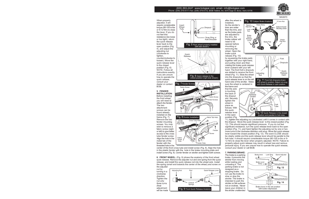
Fig. 10
after the wheel is installed).
As the stroller’s tires are wider than the rims, and as the brake pads
are adjusted to the rims, the
brake caliper will need to be opened before
mounting or removing the wheel. Open the
brake quick release (Fig. 10)
by squeezing the brake pads
together with your right hand, and pulling down and then
rotating the brake quick release lever outward with your left hand. The front fork’s dropouts
are slotted to receive the front wheel (Fig. 11). Slide the wheel into the dropouts so that the quick release lever is on the left hand side of the stroller. Make sure the wheel is centered in the frame and
that the axle is touching
the back of the dropout
slot. Securely tighten the
wheel in place as
follows: With the quick release lever in the open position (Fig.
11), tighten the adjusting nut (clockwise) until it comes in contact with the dropout. Move the quick release lever to the closed position (Fig. 12). This should require significant pressure. If you do not feel significant resistance, turn the quick release lever back to the open position (Fig. 11), and hand tighten the adjusting nut by one or two more turns in the clockwise direction until snug. Move the quick release lever toward the closed position (Fig. 12). The word CLOSE should be clearly visible and the quick release lever should be parallel to the fork tube. It should require considerable torque (80-105in-lbs or 9- 12 Nm) to close the lever when properly adjusted. NOTE: Failure to properly adjust quick release may result in wheel loss and serious personal injury. If you are unsure how to operate the quick release, consult your dealer or call BOB.
Fig. 12 Quick Release in the closed position and parallel to fork tube.
Fork
Tube
Fig. 11 Front fork dropouts shown with wheel in position. Adjust nut snug with Quick Release in open position.
Adjusting
Nut
Quick
Release
Open
Dropouts
Fork
Brake Pad
Brake
Pad Nut
Brake & Fender
Mounting Screw
Brake Body
10 mm Nut
Caliper Brake Anatomy
MA0670

(800) 893-2447 www.bobgear.com email- info@bobgear.com

Phone: (208) 375-5171 Fax: (208) 375-5172, BOB Trailers, Inc. 5475 Gage St. Boise, Idaho 83706

When properly


adjusted, it will


require considerable

Insert


torque (80-105 in-lbs

Wheel


Dropout

or 9-12 Nm) to close

Fully


the lever. If you do


not feel this


resistance (too loose


Snap Ring or

or too tight), return


Axle Shoulder

the quick release


lever back to the


Fig. 5 Rear wheel properly installed

open position (Fig.


(left side shown).

4), and adjust the


adjusting nut


(clockwise to


Quick


tighten,


Release


counterclockwise to


loosen). Move the


quick release lever


to the closed


position (Fig. 6).


NOTE: Follow all


instructions exactly.


If you are unsure


Fig. 6 Quick release in the

how to operate the


closed position (right side shown).

quick release,


consult your

Fig. 7 Fender Screws


dealer or contact


BOB.

Fabric Screw


5. FENDER


INSTALLATION:


Before installing


Fabric Screw

the front wheel,


Fender Screws

you will need to


attach the fender.


The two


attachment


screws can be


found already


installed on the

Fig. 8 Fender Installation


frame (Fig. 7).

Metal Tab Hole

Remove the two

Brake

Cross Tube Hole


fender mounting


Mounting


screws. You may

Plate Hole


wish to remove a


fabric screw (right


Fender

or left) to give better


access to the cross


Screw

tube fender screw.

Fabric


Align the hole in the


metal tab of the

Screw


Hole


fender with the


Fender Hole

threaded hole in the


center of the front cross tube and install screw (Fig. 8). Align the hole

in the plastic fender with the hole in the brake mounting plate and

install screw (Fig. 8). Center fender on stroller and tighten both screws.

6.FRONT WHEEL: (Fig. 9) shows the anatomy of the front wheel quick release. Remove the adjuster nut and one spring from the quick release, and install the quick release rod into the wheel axle. Install the spring (small end towards the center of the wheel) and screw on the adjuster

nut by

Adjusting Nut

Rod

Quick Release Lever

turning in a


clockwise


direction.


Tighten the


nut only


Conical


three turns


(final


Springs

Cam Housing


adjustment

Fig. 9 Front Quick Release Anatomy

will be made


7.PARKING BRAKE: The brake is a parking brake, it prevents the stroller from moving while loading and unloading it. The parking brake is not designed as a stopping brake. Do not use the brake to slow or stop the stroller. The brake is intended to park the stroller on flat surfaces not on inclines. Never leave your children in the stroller unattended

Brake lever

Lock Ring

Barrel Adjuster

Brake Lever


Body


ParkingBrakeButton


Fig. 13


ParkingBrakeButton


Fig. 14

Brake lever in the set position

with button depressed.

Page 2
Image 2
BOB MA0501A operating instructions Fender Installation, Rear wheel properly installed

MA0501A specifications

The BOB MA0501A is a cutting-edge electronic module designed for modern applications in various fields, including robotics, automation, and IoT (Internet of Things). This versatile device is equipped with an array of features, technologies, and characteristics that make it an invaluable component for developers and engineers.

One of the standout aspects of the BOB MA0501A is its compact design. Measuring only a few centimeters in size, it allows for easy integration into limited spaces without compromising performance. This small footprint makes it ideal for applications where space is at a premium, such as wearable devices and compact robotic systems.

The BOB MA0501A comes with a powerful microcontroller that supports a wide range of programming languages, enhancing accessibility for developers with varied skill sets. The onboard microcontroller typically operates at speeds exceeding 16 MHz, ensuring efficient processing capabilities necessary for real-time applications. Furthermore, it supports various communication protocols, including UART, I2C, and SPI, enabling seamless connectivity with other devices.

Another important feature of the BOB MA0501A is its extensive range of input and output pins. This flexibility allows users to connect numerous sensors, actuators, and additional components, expanding the module's capabilities for diverse applications. The digital input/output pins can handle multiple voltage levels, accommodating different electronic components.

In terms of power efficiency, the BOB MA0501A is designed to operate within a wide voltage range, typically from 3.3V to 5V. This adaptability makes it compatible with standard battery systems, as well as power supplies commonly found in various electronic projects.

The BOB MA0501A also incorporates advanced security and data protection features. This is particularly important for IoT applications, where data integrity and protection against unauthorized access are critical concerns. Built-in encryption functionalities help safeguard sensitive information during data transmission.

Additionally, the BOB MA0501A is designed with modularity in mind, allowing for easy upgrades and modifications. This characteristic ensures that developers can adapt their projects to evolving technological needs without requiring a complete redesign. The combination of its robustness, functionality, and ease of use positions the BOB MA0501A as an excellent choice for both hobbyists and professionals looking to innovate in their projects.