ANS1R specifications
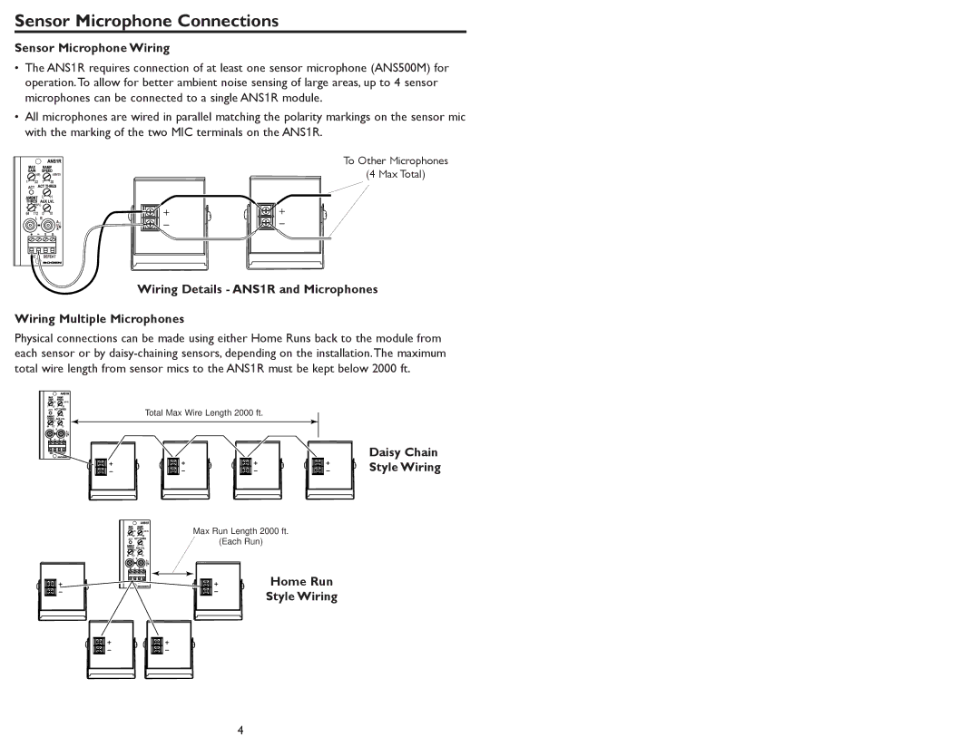
The Bogen ANS1R is a versatile and powerful audio solution designed for public address and sound reinforcement applications. Known for its robust features and innovative technologies, the ANS1R is ideal for a variety of settings, from schools and auditoriums to warehouses and outdoor events.One of the main features of the Bogen ANS1R is its 1,000-watt power capability, delivering clear and reliable sound coverage over a substantial area. This power output ensures that announcements are heard loud and clear, even in noisy environments. The built-in transformer allows for easy integration into existing audio systems, making it a flexible choice for various installations.
The system boasts an advanced digital signal processor (DSP) that enhances audio quality and provides users with a range of customizable settings. With this technology, users can tailor the sound output to suit specific acoustical environments, optimizing clarity and reducing distortion. The ANS1R includes multiple sound presets, making it easy to switch settings based on the requirements of different events, from spoken word to music playback.
The ANS1R also features a built-in mixer with multiple channel inputs, providing connectivity for microphones, instruments, and other audio sources. This allows for seamless integration with a variety of devices, facilitating live performances or presentations. Additionally, the mixer includes EQ controls, enabling users to fine-tune the audio experience for optimal sound reproduction.
Durability is another hallmark of the Bogen ANS1R. Its rugged construction ensures that the system can withstand the rigors of heavy use, making it a reliable choice for both permanent installations and temporary setups. The device is designed for easy transport, with built-in handles and a lightweight chassis, catering to those who need to set up and disassemble equipment frequently.
In terms of connectivity, the ANS1R offers multiple output options, including balanced and unbalanced outputs, making it compatible with a wide range of audio equipment. Additionally, its industry-standard connectors simplify integration into existing PA systems.
In summary, the Bogen ANS1R stands out for its powerful performance, advanced audio processing capabilities, and rugged design. It serves as a comprehensive solution for anyone in need of a reliable and adaptable sound reinforcement system, ensuring high-quality audio across various applications.

