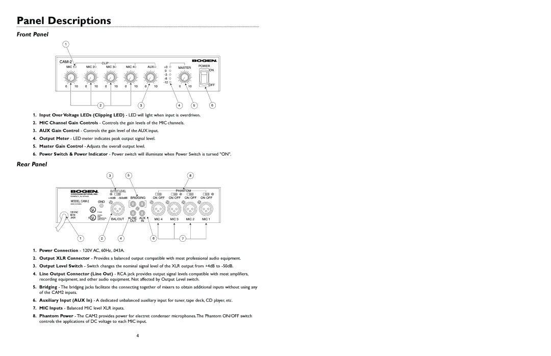
CAM2 specifications
Bogen CAM2 is a cutting-edge intercom system designed to enhance communication in educational institutions, corporate environments, and various other settings. This versatile device is particularly valued for its reliability, ease of use, and advanced technology, making it an ideal choice for modern communication needs.One of the main features of the Bogen CAM2 is its robust audio quality. The system utilizes advanced digital signal processing to ensure clear and crisp audio transmission, minimizing distortion and enhancing voice clarity. This high-quality sound output is crucial in settings where clear communication is necessary, such as classrooms, conference rooms, and public areas.
Another significant characteristic of the Bogen CAM2 is its scalability. The system can accommodate various configurations, allowing users to expand their intercom network as needed. Whether a small installation for a single building or a large-scale deployment across multiple campuses, the Bogen CAM2 can efficiently adapt to the requirements of diverse environments.
The Bogen CAM2 incorporates powerful technologies such as Voice over IP (VoIP), which enables seamless integration with existing network infrastructure. This feature not only simplifies installation but also enhances flexibility, allowing users to connect various devices while maintaining reliable communication channels. Moreover, the system is compatible with both wired and wireless setups, providing further options for deployment.
Robust security features are also integral to the Bogen CAM2 system. It includes encryption protocols that safeguard communications, ensuring that sensitive information remains protected from unauthorized access. As safety becomes an increasing concern in various settings, the Bogen CAM2 addresses these issues with effective security measures.
User-friendliness is another defining trait of the Bogen CAM2. The interface is designed for intuitive operation, which minimizes training time and encourages widespread adoption across all user levels. From students in classrooms to employees in corporate environments, all users can easily navigate the system.
Additionally, the Bogen CAM2 offers various connectivity options, supporting both traditional intercom devices and modern IP-based solutions. This feature makes it suitable for hybrid systems where both old and new technologies coexist.
In summary, the Bogen CAM2 stands out as a sophisticated intercom system that combines audio excellence, scalability, and advanced technologies. Its security features, user-friendly interface, and adaptability make it a top choice for institutions looking to enhance their communication capabilities effectively.

