GS-35, GS-250, GS-100, GS-60, GS-150 specifications
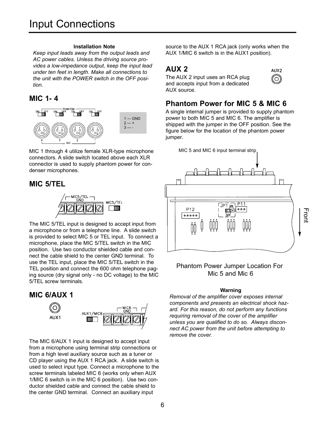
The Bogen GS series offers a variety of versatile and efficient amplifiers tailored for different audio applications. Among the models in the series are the GS-250, GS-100, GS-35, GS-150, and GS-60, each providing unique features suited for various environments, such as schools, auditoriums, and commercial settings.The Bogen GS-250 is a robust amplifier, delivering a powerful output of 250 watts. Its key feature is its built-in 5-input mixing capability, allowing for seamless integration of multiple audio sources. The GS-250 incorporates advanced thermal protection and a low-impedance output, ensuring reliable performance even under strenuous conditions. This model also supports both 70V and 4Ω speaker configurations, making it adaptable for a wide range of installations.
Next in the lineup is the GS-100, which outputs 100 watts and is designed for medium-sized venues. It features a straightforward front-panel interface with volume controls and indicator lights for easy operation. The GS-100 is equipped with two auxiliary inputs, enabling users to connect additional devices, such as microphones or digital audio players, while its built-in paging capabilities make it suitable for announcements in public spaces.
The GS-35 is a compact model with a 35-watt output, ideal for small rooms or personal use. This amplifier includes a single microphone input with an adjustable volume control, making it user-friendly for educational settings or small business environments. Its lightweight design allows for easy transportation and installation, offering a practical solution for localized sound needs.
For slightly larger applications, the GS-150 offers 150 watts of power. This model is equipped with multiple inputs, including dedicated microphone and auxiliary options. An important feature of the GS-150 is its user-adjustable tone control, providing flexibility to tailor sound quality based on the acoustics of the environment. Additionally, it supports both high-impedance and low-impedance systems.
Finally, the GS-60 rounds out the series with its 60-watt output, perfect for smaller venues. It boasts a simple setup with an intuitive interface, catering to users who may not be audio professionals. The GS-60 combines affordability with quality sound reproduction, making it a popular choice for businesses looking to enhance their audio capabilities without breaking the bank.
In summary, the Bogen GS series offers a comprehensive range of amplifiers that cater to various needs, characterized by robust power outputs, multiple input options, and user-friendly interfaces. Each model is designed with reliability in mind, ensuring consistent performance in diverse audio environments.

