M300 specifications
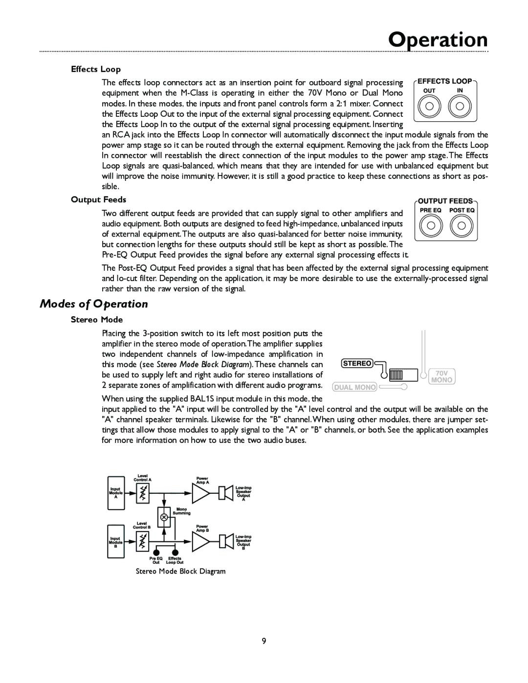
The Bogen M300 is a versatile and powerful public address system designed for a wide range of applications, including schools, churches, auditoriums, and outdoor events. Its robust design and advanced features make it an ideal choice for anyone looking to enhance their audio experience.One of the standout features of the Bogen M300 is its high-quality audio performance. The system is equipped with a 300-watt amplifier that delivers clear and powerful sound, ensuring that every announcement or musical performance is heard loud and clear. The built-in EQ settings allow users to fine-tune the audio output for different environments, providing flexibility in various settings.
The M300 is also designed for ease of use. Its intuitive interface includes straightforward controls, allowing users to quickly adjust volume levels, tone quality, and other settings without any hassle. Additionally, the system includes a variety of input options, such as XLR and 1/4-inch inputs, which enable compatibility with a wide range of microphones and audio sources.
Another notable characteristic of the Bogen M300 is its portability. Weighing only a fraction of what traditional PA systems do, the M300 can be easily transported from one location to another. Its rugged construction ensures durability, making it suitable for use in both indoor and outdoor settings.
The M300 is also equipped with advanced technologies, including built-in Bluetooth connectivity, allowing users to stream audio wirelessly from their devices. This feature makes it easy to play background music or audio files without the need for cumbersome cables.
Safety and reliability are also a priority for Bogen, and the M300 comes with integrated protection features that prevent overheating and short-circuiting. This ensures that the system operates smoothly, even during extended use.
Overall, the Bogen M300 stands out as a powerful and flexible public address system. With its high-quality audio performance, user-friendly design, and portable nature, it’s an excellent choice for anyone in need of a reliable audio solution. Whether you're presenting in a classroom, performing in a park, or delivering a sermon in a church, the Bogen M300 is engineered to meet your audio needs effectively.

