PI35A specifications
The Bogen PI35A is a versatile and high-performance amplifier that is designed for commercial sound reinforcement applications. With its robust construction and advanced features, the PI35A is perfect for schools, conference rooms, and various public address environments.One of the main features of the Bogen PI35A is its powerful 35-watt output capability. This ensures that audio can be delivered at a sufficient volume to cover medium-sized areas, making it an ideal choice for both speech and music playback. The amplifier is designed to provide clear and intelligible sound, which is essential for effective communication in any setting.
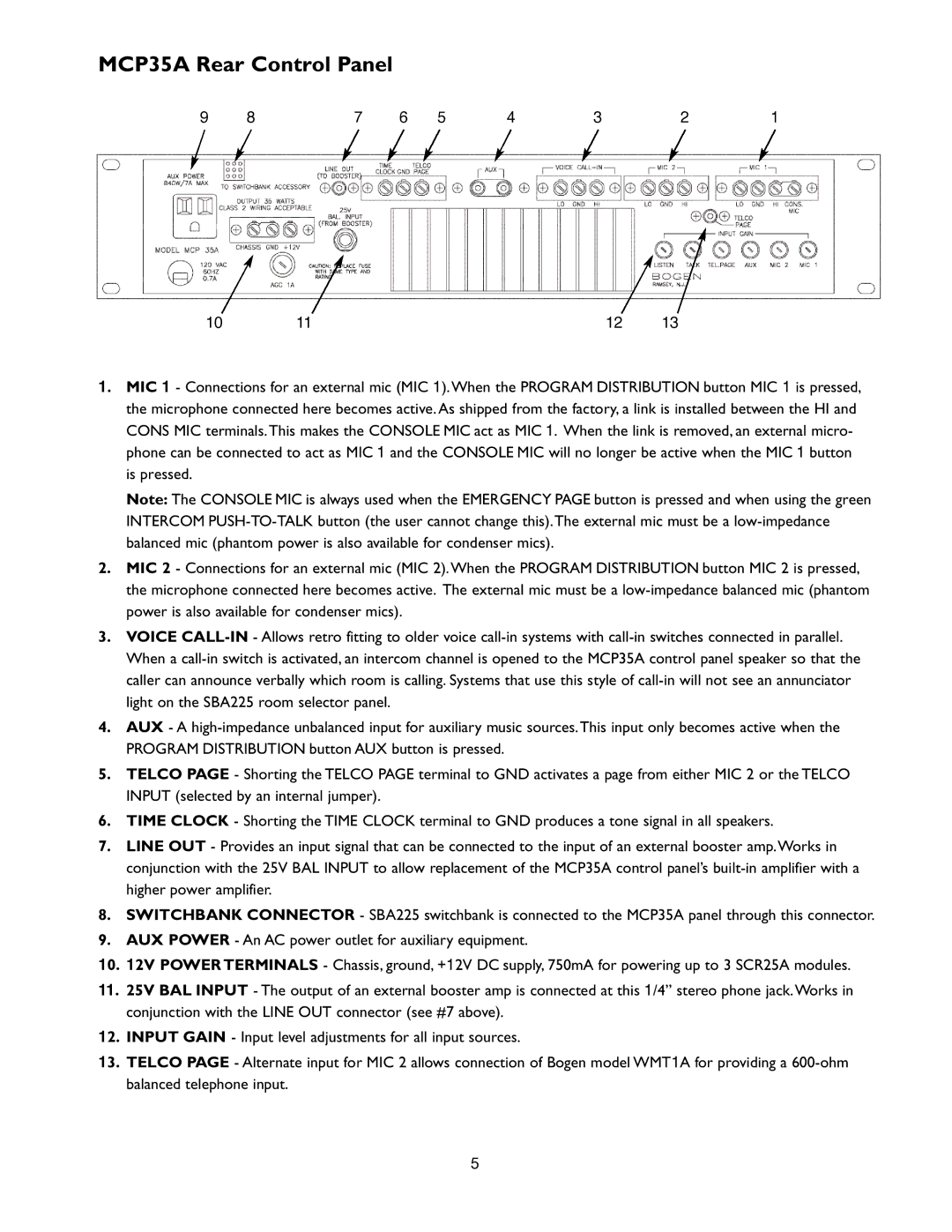
The PI35A also boasts a range of input options, including microphone, line-level, and auxiliary inputs. This flexibility allows users to connect various audio sources, such as microphones for live speaking engagements, mixing consoles, or even portable media players. The built-in tone controls, including bass and treble adjustments, enable users to tailor the audio output to suit their specific needs and preferences.
Technologically speaking, the Bogen PI35A incorporates advanced circuit designs to ensure reliability and longevity. The amplifier includes built-in protection circuitry that safeguards against overloads, short circuits, and overheating, allowing it to operate efficiently in demanding environments. Additionally, the amplifier operates quietly, ensuring that background noise does not interfere with important announcements or presentations.
One of the standout characteristics of the PI35A is its compact and lightweight design. Weighing in at just a few pounds, this amplifier can be easily mounted in various configurations, whether it be on a rack or wall-mounted, optimizing space while maintaining accessibility. The durable enclosure is engineered to withstand the rigors of installation in busy public areas.
In conclusion, the Bogen PI35A is a reliable and feature-rich amplifier that offers flexibility and excellent sound quality for various applications. Its combination of powerful output, multiple input options, advanced protection circuitry, and compact design makes it a solid choice for users seeking a high-performance sound reinforcement solution. Whether used for educational purposes, corporate events, or public announcements, the PI35A delivers a professional audio experience tailored to meet diverse needs.

