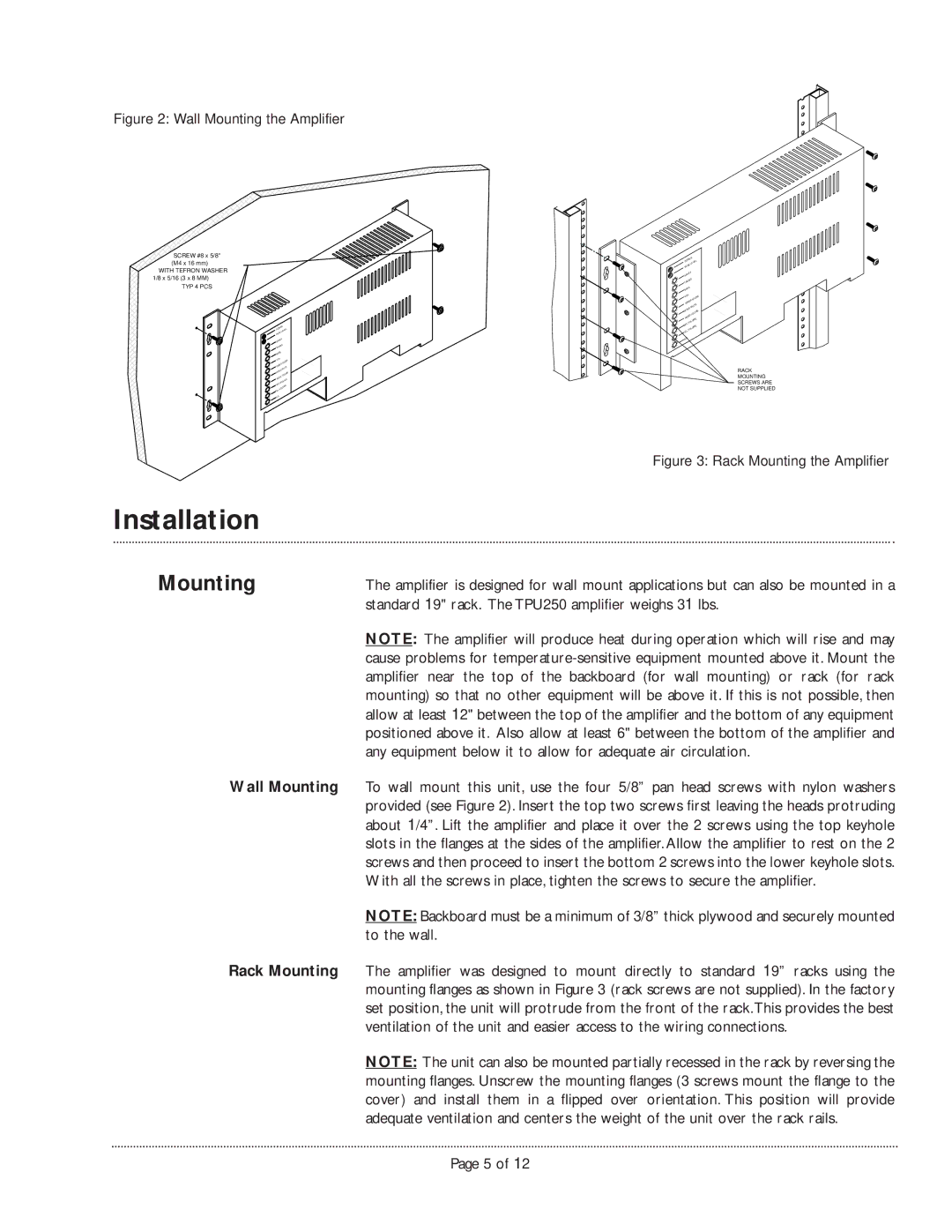
Figure 2: Wall Mounting the Amplifier
SCREW #8 x 5/8" (M4 x 16 mm)
WITH TEFRON WASHER 1/8 x 5/16 (3 x 8 MM)
TYP 4 PCS
POWER | |||
PEAK | LEVEL | ||
| |||
APHEX | |||
TREBLE | |||
BASS |
| ||
VOX | VOLUME | ||
RINGER | |||
MUTE | |||
MUSIC | |||
VOLUME | |||
MUSIC | |||
| |||
MIC | VOLUME | ||
TEL | VOLUME | ||
ALC |
|
| |
.........................
....................
POWER | ||||
PEAK | LEVEL | |||
APHEX |
| |||
TREBLE | ||||
BASS |
|
| ||
VOX |
| VOLUME | ||
RINGER | ||||
| ||||
MUSIC | MUTE | |||
VOLUME | ||||
MUSIC | ||||
|
| |||
MIC | VOLUME | |||
TEL | VOLUME | |||
|
|
| ||
ALC |
|
| ||
.........................
....................
RACK
MOUNTING
SCREWS ARE
NOT SUPPLIED
| Figure 3: Rack Mounting the Amplifier |
Installation |
|
Mounting | The amplifier is designed for wall mount applications but can also be mounted in a |
| standard 19" rack. The TPU250 amplifier weighs 31 lbs. |
| NOTE: The amplifier will produce heat during operation which will rise and may |
| cause problems for |
| amplifier near the top of the backboard (for wall mounting) or rack (for rack |
| mounting) so that no other equipment will be above it. If this is not possible, then |
| allow at least 12" between the top of the amplifier and the bottom of any equipment |
| positioned above it. Also allow at least 6" between the bottom of the amplifier and |
| any equipment below it to allow for adequate air circulation. |
Wall Mounting | To wall mount this unit, use the four 5/8” pan head screws with nylon washers |
| provided (see Figure 2). Insert the top two screws first leaving the heads protruding |
| about 1/4”. Lift the amplifier and place it over the 2 screws using the top keyhole |
| slots in the flanges at the sides of the amplifier. Allow the amplifier to rest on the 2 |
| screws and then proceed to insert the bottom 2 screws into the lower keyhole slots. |
| With all the screws in place, tighten the screws to secure the amplifier. |
| NOTE: Backboard must be a minimum of 3/8” thick plywood and securely mounted |
| to the wall. |
Rack Mounting | The amplifier was designed to mount directly to standard 19” racks using the |
| mounting flanges as shown in Figure 3 (rack screws are not supplied). In the factory |
| set position, the unit will protrude from the front of the rack.This provides the best |
| ventilation of the unit and easier access to the wiring connections. |
| NOTE: The unit can also be mounted partially recessed in the rack by reversing the |
| mounting flanges. Unscrew the mounting flanges (3 screws mount the flange to the |
| cover) and install them in a flipped over orientation. This position will provide |
| adequate ventilation and centers the weight of the unit over the rack rails. |
Page 5 of 12