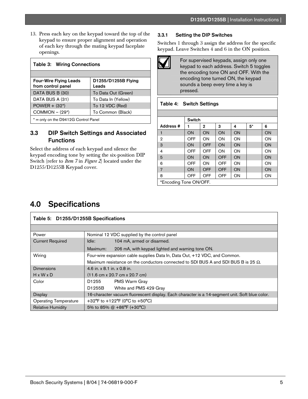
D1255, D1255B specifications
Bosch Appliances has long been synonymous with innovation and quality in home appliances. Among their impressive lineup, the Bosch D1255 and D1255B models stand out for their advanced features and dependability. These dishwashers are designed to streamline the washing process while ensuring excellent cleaning performance.The Bosch D1255 and D1255B differ slightly in their aesthetics, with the D1255 typically featuring a classic stainless-steel finish while the D1255B may come in a black or alternate finish, catering to various kitchen designs and preferences. Both models embody Bosch’s commitment to creating energy-efficient, high-performance appliances.
One of the key features of these dishwashers is their whisper-quiet operation, achieving a noise level of just 44 dBA, allowing users to run the dishwasher at any time without disturbing the household. This is made possible through advanced insulation and an efficient motor design, which both contribute to a serene kitchen environment.
The Bosch D1255 and D1255B are equipped with a flexible loading system, featuring a third rack specifically designed to maximize space for utensils and smaller items. This allows for better organization and ensures that every part of the dishwasher is utilized effectively. Additionally, the adjustable middle rack provides versatility for larger dishes, making it easier to fit in various types of cookware.
Regarding cleaning technologies, these models utilize the EcoSense feature, which automatically adjusts the wash cycle based on the load size and soil level. This smart technology not only optimizes water and energy usage but also delivers spotlessly clean dishes, prioritizing performance without compromising efficiency.
The PrecisionWash system continually scans and checks the progress of dishes throughout the cycle, ensuring that every item receives the appropriate amount of wash and rinse action. This intelligent feature guarantees optimal cleaning performance tailored to the user’s needs.
Furthermore, the Bosch D1255 and D1255B are designed with a sleek control panel that offers a range of cycle options, including intensive, auto, and quick wash settings, making it easy to customize the washing experience based on specific requirements.
In terms of durability, Bosch’s commitment to quality is evident in the stainless-steel tub that resists stains and retains heat efficiently, enhancing drying performance. The hidden heating element minimizes the risk of damage to plastics and other delicate items.
Overall, the Bosch D1255 and D1255B dishwashers embody the perfect blend of sophistication, technology, and practicality, proving to be a valuable addition to any modern kitchen. Whether you prioritize quiet operation, energy efficiency, or exceptional cleaning results, these models deliver on all fronts, making them a worthy investment for homeowners seeking excellence in their kitchen appliances.

