Bosch Appliances DS924IPET 5.0Programming General Guidelines, Walk Testing, RF Testing, 06/09

Models: DS924IPET

1 2
Download 2 pages 26.63 Kb
Page 2
Image 2
5.0Programming General Guidelines

4.2 Attaching the Enclosure

• Attach the PIR base to the mounting plate and tighten the mounting plate locking screw.

• Replace the cover, engaging the top first then securing the bottom latch.

• For added security, the cover may be locked to the base latch using the small screw provided. The screw hole in the bottom of the cover must be knocked out prior to replacing the cover.

5.0Programming General Guidelines

• Put the Control Panel in program mode.

• Trip the sensor’s tamper switch by removing its cover.

• Restore the tamper by replacing the sensor’s cover.

Refer to the appropriate Control Panel installation manual for specific instructions on programming this device.

6.0 Walk Testing

6.1 Setup

Loosen the vertical adjust screw and set the vertical adjustment to -4°.


0


S

0

8


H

4

4


I


TEST


8


VERTICAL ADJUST


-4°

SCREW


Figure 5

6.2


Sensitivity Selection

• Locate the sensitivity pins. Move the shorting jumper to the appropriate

pair of pins.

• If the shorting jumper is not used or placed incorrectly, the sensor defaults

S


to Intermediate sensitivity.


I


Standard sensitivity is required for Pet Applications. This

H


setting is the most tolerant of environmental extremes.


Intermediate sensitivity should be used for any location where an

S


intruder is expected to cover only a small portion of the protected


I


area. This setting tolerates normal environments. Do not use this

H


setting for Pet Applications.

Note: When the Walk Test Mode has ended, an alarm can be transmitted only after three (3) minutes have passed since the previous alarm. This 3 minute lockout time reduces unnecessary RF transmissions in high traffic areas thereby extending battery life.

6.5Maintenance

At least once a year, the range and coverage should be verified for proper operation. To assure daily operation, the end user should be instructed to walk through the far end of the coverage pattern to verify an alarm output prior to arming the system.

6.6Battery Installation

The sensor is normally shipped with its battery installed. If battery replacement is necessary observe proper polarity when installing a new battery or the sensor may be damaged. When the battery is replaced, wait at least 5 minutes after installing battery before activating the Walk Test Mode.

7.0 RF Testing

The actual RF transmitter range can be determined by performing a Dealer Sensor Test as follows:

• Remove the sensor’s cover and press the Walk Test Switch. Refer to Figure 3 for the switch location.

• Replace the sensor’s cover.

• Using the appropriate touchpad for the Control Panel, enter the Dealer Sensor Test Code.

• Move across the detection pattern until the sensor’s LED turns on. STOP your motion.

• Note the number of siren beeps indicating how many RF packets the control panel received from the sensor. You should hear 7-8 beeps. If you hear 6 or fewer beeps, relocate the sensor and retest.

8.0 FCC Notice

This device complies with Part 15 of the FCC Rules. Operation is subject to the following two conditions:

1. This device may not cause harmful interference.

2. This device must accept any interference, including interference that may cause undesired operation.

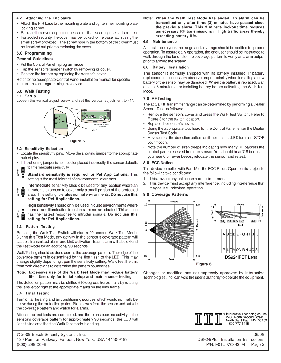
9.0 Coverage Patterns


High sensitivity should only be used in quiet environments where

S


thermal and illumination transients are not anticipated. This setting

I


has the fastest response to intruder signals. Do not use this

H


setting for Pet Applications.


6.3Pattern Testing

Pressing the Walk Test Switch will start a 90 second Walk Test Mode. During this Test Mode, any activity in the sensor’s coverage pattern will cause a transmitted alarm and LED activation. Each alarm will also extend the Test Mode for an additional 90 seconds.

Walk Testing should be done across the coverage pattern. The edge of the coverage pattern is determined by the first flash of the LED. This may change slightly depending upon the sensitivity setting. Walk Test the unit from both directions to determine the pattern boundaries.

0

20

0

20 0

Meters


L


P

M


Q

T


U

R V

N


S


O


Feet

A

11 6.5

10 0

Meters

11 3


BC


0 0


A-K 35 0

D


T-U P-S & V L-O

E


Feet


F

0


G


A B C D E F G H I J K

H


J

I

K

P L T MQ V R N U O S

35

6.5

DS924iPET Lens


Figure 6


Note: Excessive use of the Walk Test Mode may reduce battery life. Use only for initial setup and maintenance testing.

The detection pattern may be shifted ±10 degrees horizontally by rotating the lens left or right to the appropriate marks on the lens frame.

6.4Final Testing

Turn on all heating and air conditioning sources which would normally be active during the protection period. Stand away from the sensor and outside the coverage pattern and watch for alarms.

After setup and tests are completed, and there has been no activity in the sensor’s coverage pattern for approximately 90 seconds, the LED will flash to indicate that the Walk Test mode is ending.

Changes or modifications not expressly approved by Interactive Technologies, Inc. can void the user’s authority to operate the equipment.

® Interactive Technologies, Inc.

2266 North Second Street

North Saint Paul, MN 55109

1-800-777-1415

© 2009 Bosch Security Systems, Inc.

06/09

130 Perinton Parkway, Fairport, New York, USA 14450-9199

DS924iPET Installation Instructions

(800) 289-0096

P/N: F01U070392-04 Page 2

Page 2
Image 2
Bosch Appliances DS924IPET 5.0Programming General Guidelines, Walk Testing, RF Testing, FCC Notice, Coverage Patterns