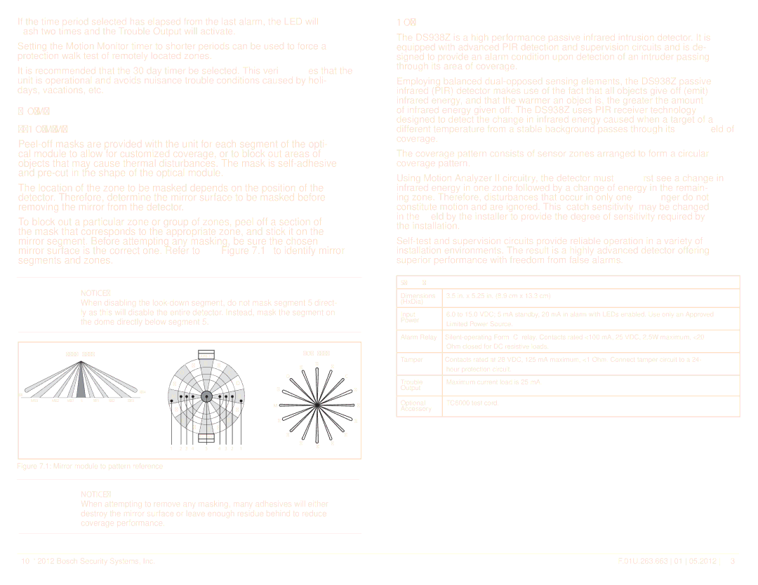
DS938Z specifications
The Bosch Appliances DS938Z dishwasher stands out in the market for its combination of efficiency, technological innovation, and elegant design. As part of Bosch's renowned lineup, this model is designed to cater to modern kitchen needs while ensuring an eco-friendly approach.One of the key features of the DS938Z is its impressive energy efficiency. With an ENERGY STAR® certification, it not only helps reduce utility bills but also minimizes its environmental impact. The dishwasher consumes significantly less water compared to traditional models, thanks to Bosch's advanced sensor technology that optimally adjusts the water usage based on the load size. This ensures that users can enjoy pristine dishes without worrying about resource wastage.
The DS938Z also employs Bosch's patented Silence Technology, which includes sound-reduction components that allow the appliance to operate quietly, often below 44 dBA. This low noise level makes it ideal for open-concept kitchen and living spaces, providing a peaceful environment even during operation. Users can carry on conversations or watch TV without being disturbed by the dishwasher.
Another outstanding feature is the flexibility in arrangement and loading. The Bosch DS938Z boasts an adjustable third rack, providing additional space for utensils and smaller items without sacrificing capacity on the lower racks. The rack system is designed with multiple configurations, allowing for easy loading and unloading, accommodating various dish sizes, shapes, and types.
The dishwasher also incorporates a powerful wash system that utilizes various spray arms to ensure comprehensive cleaning coverage. With multiple wash cycles to choose from, including options for heavy-duty cleaning or quick washes, users can tailor the washing process according to their specific needs. The Auto Cycle is a standout feature, where the dishwasher automatically detects the soil level and adjusts the wash settings to optimize performance.
Moreover, the DS938Z utilizes a stainless steel tub, which is not only durable but also enhances the drying process with its insulation properties. The heating element is designed to heat water to a higher temperature, enabling efficient drying without the need for excessive energy use.
In summary, the Bosch Appliances DS938Z dishwasher combines cutting-edge technology, energy efficiency, and flexibility in use, making it a top choice for environmentally conscious consumers seeking convenience in their kitchen. Its silent operation, innovative features, and sleek design make it a valuable addition to any modern home.

