Bosch Appliances IN30125 Disposal, Maintenance, Wiring Grounding, Bypass Diodes, english

Models: IN30125

1 7
Download 7 pages 53.53 Kb
Page 6
Image 6
10  Wiring  Grounding

10 Wiring Grounding

The term “array” is used to describe the assembly of

several modules on a support structure with associ-

ated wiring. Use copper wire that is sunlight resistant

and is insulated to withstand the maximum possible

system open circuit voltage. Check your local codes

for requirements.

Use system wiring with suitable cross-sectional areas

and connectors that are approved for use at the

maximum short-circuit current of the module.

The maximum open circuit voltage of the system

must not be greater than the specified maximum

system voltage for the module.

When reverse currents can exceed the value of the

maximum protective fuse marked on the back of the

module, a properly rated and certified over current

device (fuse or circuit breaker) must be connected in

series with each module or string of modules.

The fuse used is a glass / HRC type of rating 15

Amps. The fuse rating has to begreater than or equal

to 135 % of the module’s short circuit current.

The rating of the over-current device shall not exceed

the value of the maximum protective fuse marked on

the back of the module.

Match the polarities of cables and terminals when

en

8Grounding

8Grounding Important Notice!

Bonding connection

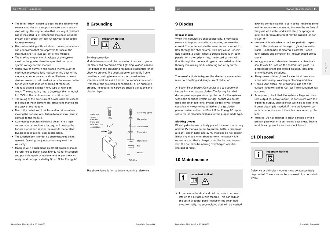
Module frames should be connected to an earth ground for safety and protection from lightning. A good connec- tion between the grounding hardware is essential for an effective ground. The anodization on a module frame provides a coating to minimize the corrosion due to weather and it acts as a barrier that reduces the effec- tiveness of the grounding connection. For an adequate ground, the grounding hardware should pierce the ano- dization layer.

en

9 Diodes

Bypass Diodes

When the modules are shaded partially, it may cause reverse voltage across cells or modules, because the current from other cells in the same series is forced to flow through the shaded area. This may cause undesir- able heating to occur. When a bypass diode is wired in parallel with the series string, the forced current will flow through the diode and bypass the shaded module, thereby minimizing module heating and array current losses.

The use of a diode to bypass the shaded area can mini- mize both heating and array current reduction.

All Bosch Solar Energy AG modules are equipped with factory installed bypass diodes. The factory installed diodes provide proper circuit protection for the systems within the specified system voltage, so that you do not need any other additional bypass diodes. If your system specifications require you to add or change diodes, please contact authorized Bosch Solar Energy AG repre-

Diodes Maintenance 11

away by periodic rainfall, but in some instances some


maintenance is recommended to clean the surface of


the glass with water and a soft cloth or sponge. A


mild non-abrasive detergent may be applied for per-


sistent dirt.


However it is advisable to perform periodic inspec-


tion of the modules for damage to glass, back-skin,


frame, junction box or external electrical / loose


connections and corrosion by the authorized profes-


sional.


No aggressive and abrasive cleansers or chemicals

english

should ever be used on the coated front glass. No

alkali based chemicals should be used, including

ammonia based solutions.


Always wear rubber gloves for electrical insulation


while maintaining, washing or cleaning modules.


Once a year, check that growing foliage has not


caused module shading. Correct if this condition has


occurred.


As required, check that the system voltage and cur-


rent output (or power output) is consistent with the


expected output. Such a check will help to determine


if array cleaning is needed, if there are loose or cor-


roded connections, or if there is a component prob-


making the connections; failure todo so may result in

damage to the module.

Connecting modules in reverse polarity to a high

current source, such as a battery, will destroy the

bypass diodes and render the module inoperative.

Bypass diodes are not user replaceable.

The junction box is under no circumstances being

opened. Opening the junction box may void the

warranty.

Modules with a suspected electrical problem should

Place cup washer between frame and wire with con- caveside up

Grounding Screw

Flat washer

Ground Wire

Cup washer

Star washer

Nut

sentative for recommendations for the proper diode type.

Blocking Diodes

Blocking diodes are typically placed between the battery and the PV module output to prevent battery discharge at night. Bosch Solar Energy AG modules do not contain a blocking diode when shipped from the factory. It is recommended that a charge controller be used to pre- vent the batteries from being overcharged and dis- charged at night.

lem.

Warning: Do not attempt to clean a module with a

broken glass over or a perforated backsheet. Such a

module can present a serious shock hazard.

11 Disposal

be returned to Bosch Solar Energy AG for inspection

and possible repair or replacement as per the war-

ranty conditions provided by Bosch Solar Energy AG.

Frame

Side View

The above figure is for hardware mounting reference.

10 Maintenance

Important Notice!

It is common for dust and dirt particles to accumu- late on the surface of the module. This can reduce the optimal output performance of the solar mod- ules. Normally, the accumulated dust will be washed

Important Notice!

Defective or old solar modules must be appropriately disposed of. These may not be disposed of in household waste.

Bosch Solar Module c-Si M 60 IN30125

      Bosch Solar Energy AG

Bosch Solar Module c-Si M 60 IN30125

      Bosch Solar Energy AG

Page 6
Image 6
Bosch Appliances IN30125 Disposal, Wiring Grounding, Bypass Diodes, Diodes Maintenance, Blocking Diodes