Manuals
/
Bosch Appliances
/
Home Audio
/
Radio
Bosch Appliances
FLM-I, S, 420
manual
Models:
FLM-I
420
S
1
2
4
4
Download
4 pages
33.5 Kb
1
2
3
4
Configuration
Accessories
Page 2
Image 2
Page 1
Page 3
Page 2
Image 2
Page 1
Page 3
Contents
Address switch rotary switch
Features of improved LSN
Connector
Configuration
Page
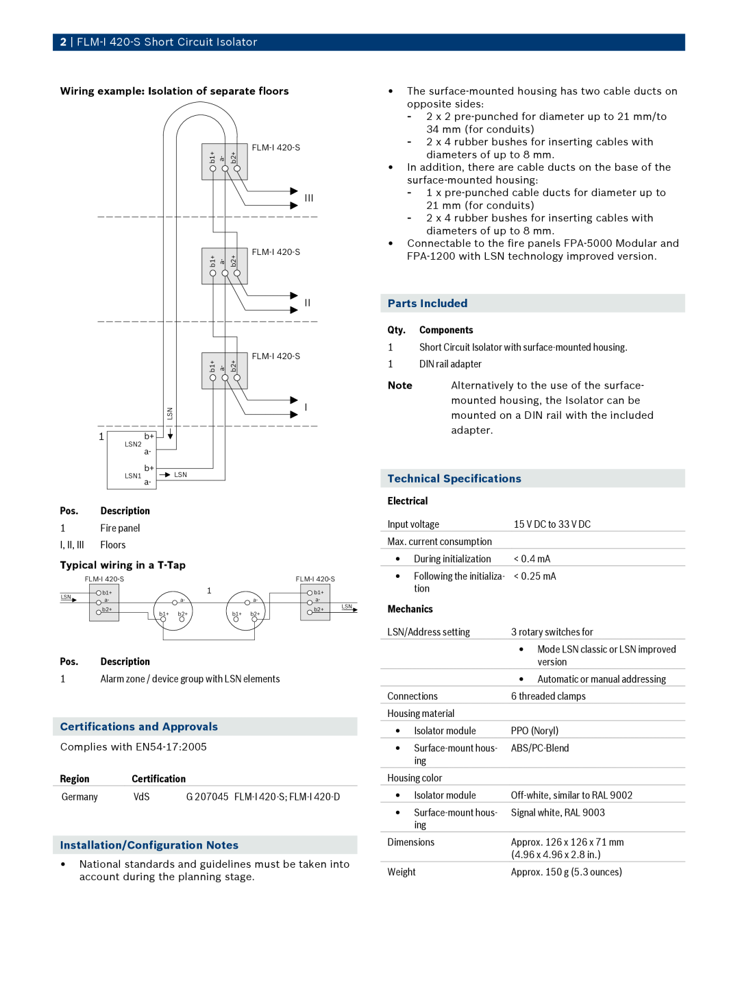
FLM‑I 420‑S Short Circuit Isolator
for the isolation of alarm zones in which a
Accessories
Ordering Information
Europe, Middle East, Africa
4 FLM‑I 420‑S Short Circuit Isolator
Americas
Asia-Pacific
Top
Page
Image
Contents