BM 2609140889
Assembly
Disconnect battery pack ! WARNING from tool before making any
assembly, adjustments or changing accessories. Such preventive safety measures reduce the risk of starting the tool accidentally.
INSERTING AND REMOVING
ACCESSORIES
!WARNING To avoid loss of control, ensure bit is locked in chuck
by pulling on bit after it has been inserted.
The chuck accepts only standard 1/4" hexagonal shank accessories with power groove.
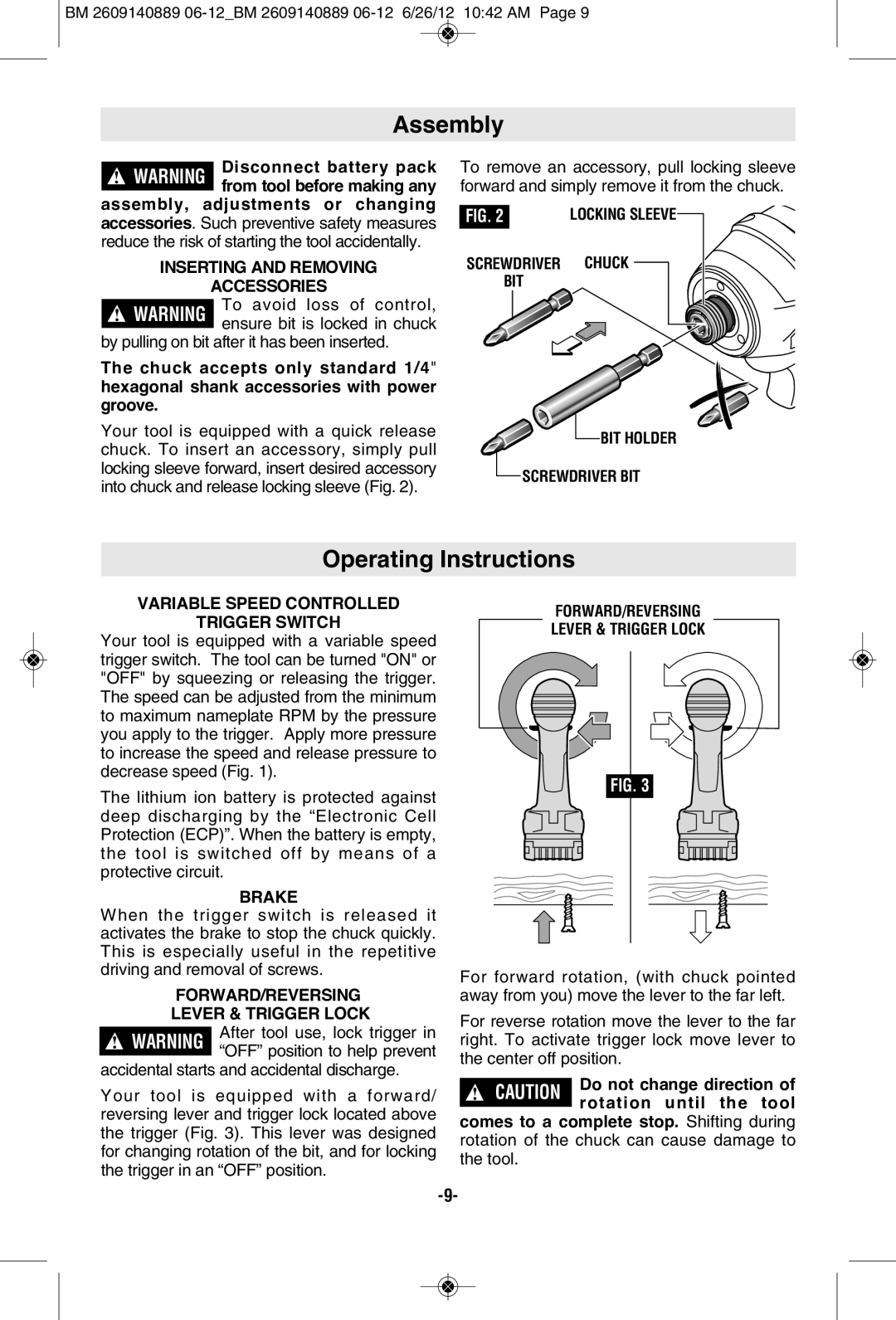
Your tool is equipped with a quick release chuck. To insert an accessory, simply pull locking sleeve forward, insert desired accessory into chuck and release locking sleeve (Fig. 2).
To remove an accessory, pull locking sleeve forward and simply remove it from the chuck.
FIG. 2 | LOCKING SLEEVE |
SCREWDRIVER CHUCK
BIT
![]() BIT HOLDER
BIT HOLDER
SCREWDRIVER BIT |
Operating Instructions
VARIABLE SPEED CONTROLLED
TRIGGER SWITCH
Your tool is equipped with a variable speed trigger switch. The tool can be turned "ON" or "OFF" by squeezing or releasing the trigger. The speed can be adjusted from the minimum to maximum nameplate RPM by the pressure you apply to the trigger. Apply more pressure to increase the speed and release pressure to decrease speed (Fig. 1).
The lithium ion battery is protected against deep discharging by the “Electronic Cell Protection (ECP)”. When the battery is empty, the tool is switched off by means of a protective circuit.
BRAKE
When the trigger switch is released it activates the brake to stop the chuck quickly. This is especially useful in the repetitive driving and removal of screws.
FORWARD/REVERSING
LEVER & TRIGGER LOCK
!WARNING After tool use, lock trigger in “OFF” position to help prevent
accidental starts and accidental discharge.
Your tool is equipped with a forward/ reversing lever and trigger lock located above the trigger (Fig. 3). This lever was designed for changing rotation of the bit, and for locking the trigger in an “OFF” position.
FORWARD/REVERSING
LEVER & TRIGGER LOCK
FIG. 3
For forward rotation, (with chuck pointed away from you) move the lever to the far left.
For reverse rotation move the lever to the far right. To activate trigger lock move lever to the center off position.
! | CAUTION | Do not change direction of | |
rotation until the tool | |||
|
|
comes to a complete stop. Shifting during rotation of the chuck can cause damage to the tool.