ATR20/20 Quick Start RS485 Communications
www.acroprint.com
Before you begin
You’ll need the following hardware:
•RS485 to RS232 Converter Assembly
Junction boxes (minimum of 2 plus one box for each additional terminal)
Modular cable (minimum of 2 plus one cable for each additional terminal)
Teflon Cable (lengths available: 100', 200', 500', 1000')
•Acroprint Data Collection Terminal (ADCT) including,
•Power Supply
•Wall Mount and 4 screws
•Configuration Badge
Follow the setup instructions on this Quick Start sheet. For updates to the ATR20/20 documenta- tion and
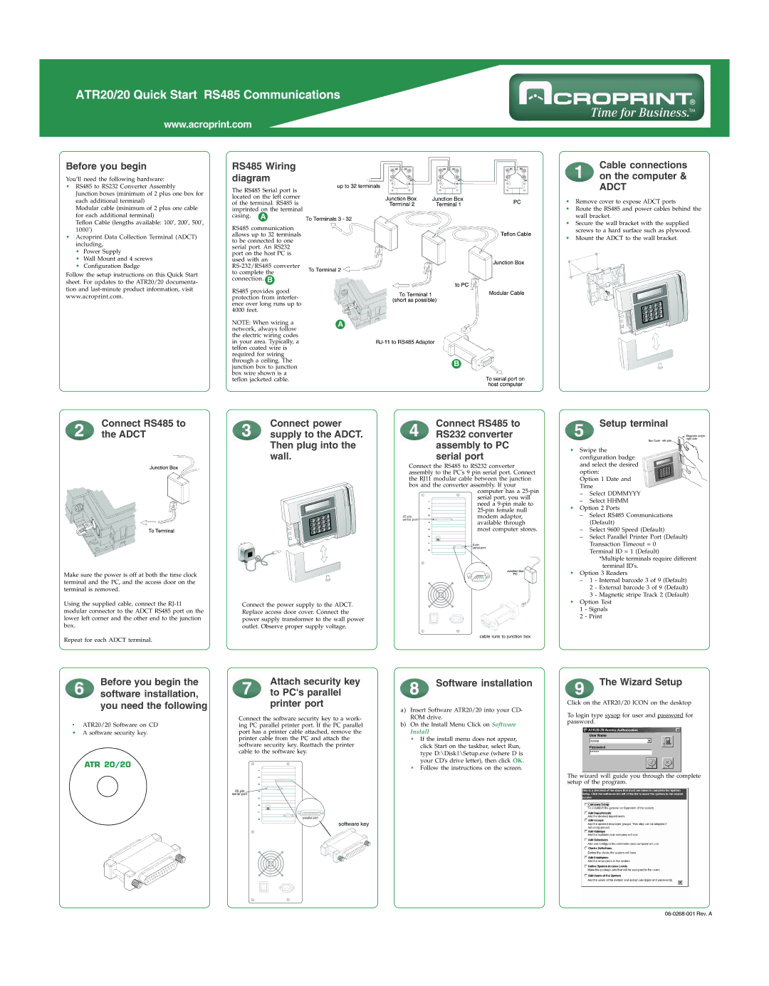
RS485 Wiring diagram
The RS485 Serial port is located on the left corner of the terminal. RS485 is imprinted on the terminal casing. A
RS485 communication allows up to 32 terminals to be connected to one serial port. An RS232 port on the host PC is used with an
RS485 provides good protection from interfer- ence over long runs up to 4000 feet.
NOTE: When wiring a | A | |
network, always follow |
| |
the electric wiring codes |
| |
in your area. Typically, a |
| |
telfon coated wire is |
| |
required for wiring |
| |
through a ceiling. The | B | |
junction box to junction | ||
| ||
box wire shown is a |
| |
teflon jacketed cable. |
|
Cable connections on the computer &
ADCT
•Remove cover to expose ADCT ports
•Route the RS485 and power cables behind the wall bracket.
•Secure the wall bracket with the supplied screws to a hard surface such as plywood.
•Mount the ADCT to the wall bracket.
Connect RS485 to | Connect power |
the ADCT | supply to the ADCT. |
| Then plug into the |
| wall. |
Make sure the power is off at both the time clock terminal and the PC, and the access door on the terminal is removed.
Using the supplied cable, connect the | Connect the power supply to the ADCT. |
modular connector to the ADCT RS485 port on the | Replace access door cover. Connect the |
lower left corner and the other end to the junction | power supply transformer to the wall power |
box. | outlet. Observe proper supply voltage. |
Repeat for each ADCT terminal. |
|
Connect RS485 to RS232 converter assembly to PC serial port
Connect the RS485 to RS232 converter assembly to the PC's 9 pin serial port. Connect the RJ11 modular cable between the junction box and the converter assembly. If your
computer has a
Setup terminal
•Swipe the configuration badge and select the desired option:
Option 1 Date and Time
–Select DDMMYYY
–Select HHMM
•Option 2 Ports
–Select RS485 Communications (Default)
–Select 9600 Speed (Default)
–Select Parallel Printer Port (Default) Transaction Timeout = 0 Terminal ID = 1 (Default)
*Multiple terminals require different terminal ID's.
•Option 3 Readers
–1 - Internal barcode 3 of 9 (Default)
2 - External barcode 3 of 9 (Default)
3 - Magnetic stripe Track 2 (Default)
•Option Test 1 - Signals 2 - Print
Before you begin the software installation, you need the following
•ATR20/20 Software on CD
•A software security key.
ATR 20/20
Attach security key to PC's parallel printer port
Connect the software security key to a work- ing PC parallel printer port. If the PC parallel port has a printer cable attached, remove the printer cable from the PC and attach the software security key. Reattach the printer cable to the software key.
software key
Software installation
a)Insert Software ATR20/20 into your CD- ROM drive.
b)On the Install Menu Click on Software
Install
•If the install menu does not appear, click Start on the taskbar, select Run, type D:\Disk1\Setup.exe (where D is your CD's drive letter), then click OK.
•Follow the instructions on the screen.
The Wizard Setup
Click on the ATR20/20 ICON on the desktop
To login type sysop for user and password for password.
The wizard will guide you through the complete setup of the program.