Dialogic®
D/82JCT-U
PBX Integration Board
Quick Install Card
Part Number:
Before You Begin
Board ID
Display
J1 ![]()
PCI bus connector
![]() Rear bracket
Rear bracket
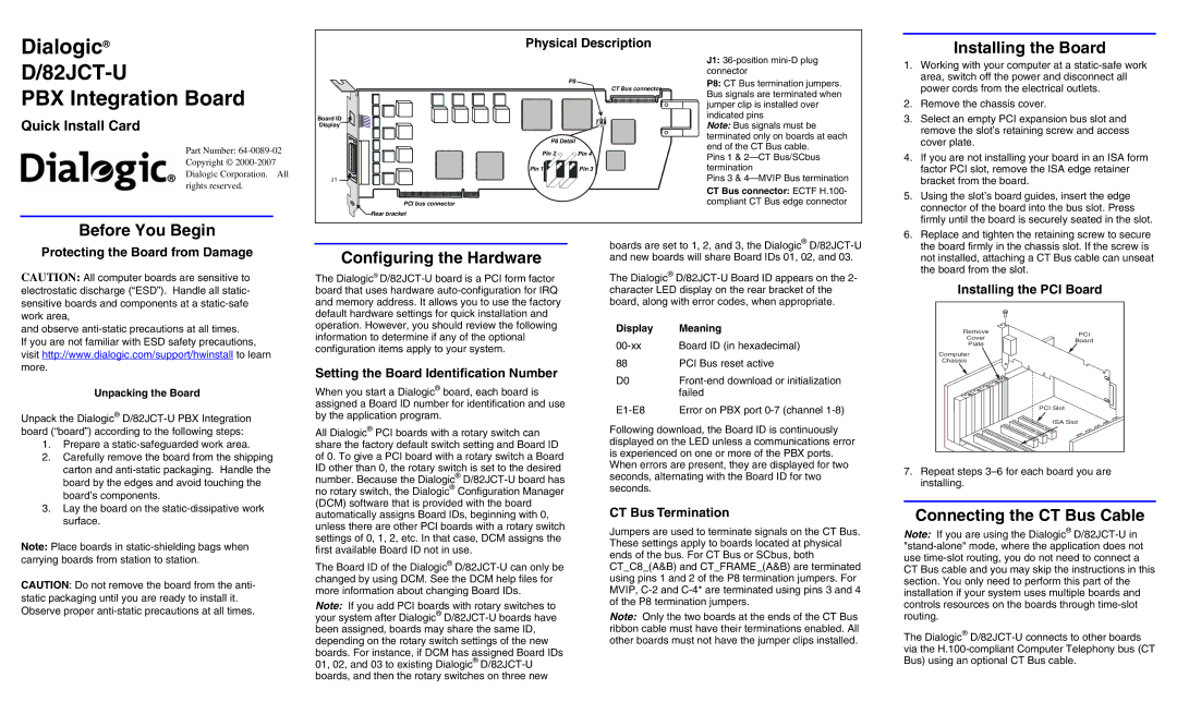
Physical Description
P8
CT Bus connector![]()
P8 Detail |
|
Pin 2 | Pin 4 |
Pin 1 | Pin 3 |
J1:
P8: CT Bus termination jumpers. Bus signals are terminated when jumper clip is installed over indicated pins
Note: Bus signals must be terminated only on boards at each end of the CT Bus cable.
Pins 1 &
Pins 3 &
CT Bus connector: ECTF H.100- compliant CT Bus edge connector
Installing the Board
1. | Working with your computer at a |
| area, switch off the power and disconnect all |
| power cords from the electrical outlets. |
2. | Remove the chassis cover. |
3. | Select an empty PCI expansion bus slot and |
| remove the slot’s retaining screw and access |
| cover plate. |
4. | If you are not installing your board in an ISA form |
| factor PCI slot, remove the ISA edge retainer |
| bracket from the board. |
5. | Using the slot’s board guides, insert the edge |
| connector of the board into the bus slot. Press |
| firmly until the board is securely seated in the slot. |
6. | Replace and tighten the retaining screw to secure |
Protecting the Board from Damage
CAUTION: All computer boards are sensitive to electrostatic discharge (“ESD”). Handle all static- sensitive boards and components at a
and observe
If you are not familiar with ESD safety precautions, visit http://www.dialogic.com/support/hwinstall to learn more.
Unpacking the Board
Unpack the Dialogic®
1.Prepare a
2.Carefully remove the board from the shipping carton and
3.Lay the board on the
Note: Place boards in
CAUTION: Do not remove the board from the anti- static packaging until you are ready to install it. Observe proper
Configuring the Hardware
The Dialogic®
Setting the Board Identification Number
When you start a Dialogic® board, each board is assigned a Board ID number for identification and use by the application program.
All Dialogic® PCI boards with a rotary switch can share the factory default switch setting and Board ID of 0. To give a PCI board with a rotary switch a Board ID other than 0, the rotary switch is set to the desired number. Because the Dialogic®
The Board ID of the Dialogic®
Note: If you add PCI boards with rotary switches to your system after Dialogic®
boards are set to 1, 2, and 3, the Dialogic®
The Dialogic®
Display | Meaning |
Board ID (in hexadecimal) | |
88 | PCI Bus reset active |
D0 | |
| failed |
Error on PBX port |
Following download, the Board ID is continuously displayed on the LED unless a communications error is experienced on one or more of the PBX ports. When errors are present, they are displayed for two seconds, alternating with the Board ID for two seconds.
CT Bus Termination
Jumpers are used to terminate signals on the CT Bus. These settings apply to boards located at physical ends of the bus. For CT Bus or SCbus, both CT_C8_(A&B) and CT_FRAME_(A&B) are terminated using pins 1 and 2 of the P8 termination jumpers. For MVIP,
Note: Only the two boards at the ends of the CT Bus ribbon cable must have their terminations enabled. All other boards must not have the jumper clips installed.
the board firmly in the chassis slot. If the screw is |
not installed, attaching a CT Bus cable can unseat |
the board from the slot. |
Installing the PCI Board
Remove | PCI | |
Cover | ||
Board | ||
Plate | ||
| ||
Computer |
| |
Chassis |
| |
| PCI Slot | |
| ISA Slot |
7.Repeat steps
Connecting the CT Bus Cable
Note: If you are using the Dialogic®
The Dialogic®