Note: Full H.100 capabilities are not available with this release of the Dialogic®
1.Attach the end connector on the ribbon cable to the CT Bus edge connector on the top edge of the first board. The connectors are designed to fit together one way only. If the connector does not seat fully on the board, turn the cable around and try again. Make sure that the colored stripe on the cable faces toward the rear bracket. (The stripe should be adjacent to pin 1 on the board connector.) To preserve the electrical integrity of the CT Bus, use a CT Bus cable with the appropriate number of connectors (“drops”). It is recommended that no more than two connectors at either end of the cable be left unused.
2.Attach the ribbon cable to the next board until all boards are connected by the cable.
Installing the CT Bus Cable
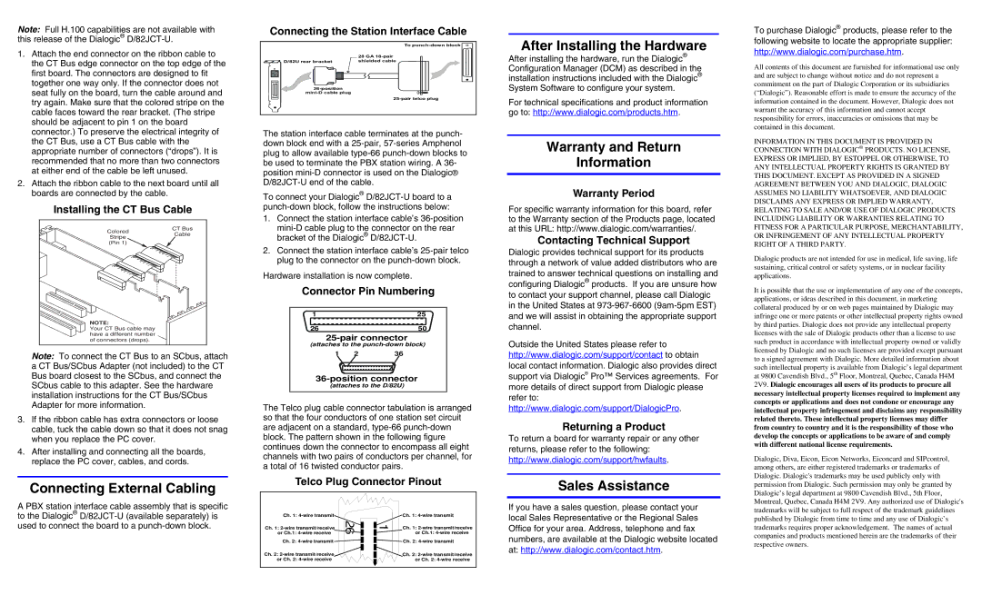
Connecting the Station Interface Cable
To
| 28 GA |
D/82U rear bracket | shielded cable |
ID
The station interface cable terminates at the punch- down block end with a
To connect your Dialogic®
After Installing the Hardware
After installing the hardware, run the Dialogic® Configuration Manager (DCM) as described in the installation instructions included with the Dialogic® System Software to configure your system.
For technical specifications and product information go to: http://www.dialogic.com/products.htm.
Warranty and Return
Information
Warranty Period
For specific warranty information for this board, refer
To purchase Dialogic® products, please refer to the following website to locate the appropriate supplier:
http://www.dialogic.com/purchase.htm.
All contents of this document are furnished for informational use only and are subject to change without notice and do not represent a commitment on the part of Dialogic Corporation or its subsidiaries (“Dialogic”). Reasonable effort is made to ensure the accuracy of the information contained in the document. However, Dialogic does not warrant the accuracy of this information and cannot accept responsibility for errors, inaccuracies or omissions that may be contained in this document.
INFORMATION IN THIS DOCUMENT IS PROVIDED IN CONNECTION WITH DIALOGIC® PRODUCTS. NO LICENSE, EXPRESS OR IMPLIED, BY ESTOPPEL OR OTHERWISE, TO ANY INTELLECTUAL PROPERTY RIGHTS IS GRANTED BY THIS DOCUMENT. EXCEPT AS PROVIDED IN A SIGNED AGREEMENT BETWEEN YOU AND DIALOGIC, DIALOGIC ASSUMES NO LIABILITY WHATSOEVER, AND DIALOGIC DISCLAIMS ANY EXPRESS OR IMPLIED WARRANTY, RELATING TO SALE AND/OR USE OF DIALOGIC PRODUCTS
Colored
CT Bus
1. Connect the station interface cable’s |
|
to the Warranty section of the Products page, located at this URL: http://www.dialogic.com/warranties/.
INCLUDING LIABILITY OR WARRANTIES RELATING TO FITNESS FOR A PARTICULAR PURPOSE, MERCHANTABILITY,
Stripe
Cable
bracket of the Dialogic® |
Contacting Technical Support
OR INFRINGEMENT OF ANY INTELLECTUAL PROPERTY
(Pin 1)
NOTE:
Your CT Bus cable may have a different number of connectors (drops).
Note: To connect the CT Bus to an SCbus, attach a CT Bus/SCbus Adapter (not included) to the CT Bus board closest to the SCbus, and connect the SCbus cable to this adapter. See the hardware installation instructions for the CT Bus/SCbus Adapter for more information.
3.If the ribbon cable has extra connectors or loose cable, tuck the cable down so that it does not snag when you replace the PC cover.
4.After installing and connecting all the boards, replace the PC cover, cables, and cords.
Connecting External Cabling
A PBX station interface cable assembly that is specific to the Dialogic®
2. Connect the station interface cable’s |
plug to the connector on the |
Hardware installation is now complete.
Connector Pin Numbering
1 |
| 25 |
26 |
| 50 |
(attaches to the | ||
1 | 2 | 36 |
| ||
(attaches to the D/82U) | ||
The Telco plug cable connector tabulation is arranged so that the four conductors of one station set circuit are adjacent on a standard,
Telco Plug Connector Pinout
Ch. 1: | Ch. 1: |
Ch. 1: | 6 | 1 | Ch. 1: | |
or Ch.1: |
| or Ch.1: | ||
Ch. 2: |
|
| Ch. 2: | |
Ch. 2: |
|
| Ch. 2: | |
or Ch. 2: |
|
| or Ch. 2: | |
Dialogic provides technical support for its products through a network of value added distributors who are trained to answer technical questions on installing and configuring Dialogic® products. If you are unsure how to contact your support channel, please call Dialogic in the United States at
Outside the United States please refer to http://www.dialogic.com/support/contact to obtain local contact information. Dialogic also provides direct support via Dialogic® Pro™ Services agreements. For more details of direct support from Dialogic please refer to: http://www.dialogic.com/support/DialogicPro.
Returning a Product
To return a board for warranty repair or any other returns, please refer to the following: http://www.dialogic.com/support/hwfaults.
Sales Assistance
If you have a sales question, please contact your local Sales Representative or the Regional Sales Office for your area. Address, telephone and fax numbers, are available at the Dialogic website located at: http://www.dialogic.com/contact.htm.
RIGHT OF A THIRD PARTY.
Dialogic products are not intended for use in medical, life saving, life sustaining, critical control or safety systems, or in nuclear facility applications.
It is possible that the use or implementation of any one of the concepts, applications, or ideas described in this document, in marketing collateral produced by or on web pages maintained by Dialogic may infringe one or more patents or other intellectual property rights owned by third parties. Dialogic does not provide any intellectual property licenses with the sale of Dialogic products other than a license to use such product in accordance with intellectual property owned or validly licensed by Dialogic and no such licenses are provided except pursuant to a signed agreement with Dialogic. More detailed information about such intellectual property is available from Dialogic’s legal department at 9800 Cavendish Blvd., 5th Floor, Montreal, Quebec, Canada H4M 2V9. Dialogic encourages all users of its products to procure all necessary intellectual property licenses required to implement any concepts or applications and does not condone or encourage any intellectual property infringement and disclaims any responsibility related thereto. These intellectual property licenses may differ from country to country and it is the responsibility of those who develop the concepts or applications to be aware of and comply with different national license requirements.
Dialogic, Diva, Eicon, Eicon Networks, Eiconcard and SIPcontrol, among others, are either registered trademarks or trademarks of Dialogic. Dialogic's trademarks may be used publicly only with permission from Dialogic. Such permission may only be granted by Dialogic’s legal department at 9800 Cavendish Blvd., 5th Floor, Montreal, Quebec, Canada H4M 2V9. Any authorized use of Dialogic's trademarks will be subject to full respect of the trademark guidelines published by Dialogic from time to time and any use of Dialogic’s trademarks requires proper acknowledgement. The names of actual companies and products mentioned herein are the trademarks of their respective owners.