BM 2610027607
Assembly
Disconnect the plug from ! WARNING the power source before
making any assembly, adjustments or changing accessories. Such preventive safety measures reduce the risk of starting the tool accidentally.
SELECTING GRINDING ACCESSORIES Before using a grinding wheel point or cone, be certain
that its maximum safe operating speed is not exceeded by the nameplate speed of the grinder. Do not exceed the recom mended wheel point or cone diameter.
INSTALLING ACCESSORIES
Be sure that the diameter of the shank is the same size
as the inside diameter of the collet.
! | CAUTION | To prevent damage to collet, | |
avoid excessive tightening of | |||
|
|
the collet nut when there is no accessory inserted.
Only use properly fitting and undamaged open- end wrenches.
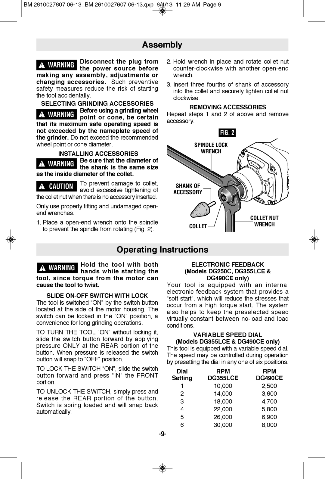
1.Place a
2.Hold wrench in place and rotate collet nut
3.Insert three fourths of shank of accessory into the collet and securely tighten collet nut clockwise.
REMOVING ACCESSORIES
Repeat steps 1 and 2 of above and remove accessory.
FIG. 2
SPINDLE LOCK
WRENCH
SHANK OF
ACCESSORY
COLLET NUT
COLLETWRENCH
Operating Instructions
!WARNING Hold the tool with both hands while starting the
tool, since torque from the motor can cause the tool to twist.
SLIDE ON-OFF SWITCH WITH LOCK
The tool is switched “ON” by the switch button located at the side of the motor housing. The switch can be locked in the “ON” position, a convenience for long grinding operations.
TO TURN THE TOOL “ON” without locking it, slide the switch button forward by applying pressure ONLY at the REAR portion of the button. When pressure is released the switch button will snap to “OFF” position.
TO LOCK THE SWITCH “ON”, slide the switch button forward and press “IN” the FRONT portion.
TO UNLOCK THE SWITCH, simply press and release the REAR portion of the button. Switch is spring loaded and will snap back automatically.
ELECTRONIC FEEDBACK
(Models DG250C, DG355LCE &
DG490CE only)
Your tool is equipped with an internal electronic feedback system that provides a “soft start”, which will reduce the stresses that occur from a high torque start. The system also helps to keep the preselected speed virtually constant between
VARIABLE SPEED DIAL
(Models DG355LCE & DG490CE only)
This tool is equipped with a variable speed dial. The speed may be controlled during operation by presetting the dial in any one of six positions.
Dial | RPM | RPM |
Setting | DG355LCE | DG490CE |
1 | 10,000 | 2,500 |
2 | 14,000 | 3,600 |
3 | 18,000 | 4,700 |
4 | 22,000 | 5,800 |
5 | 26,000 | 6,900 |
6 | 30,000 | 8,000 |
