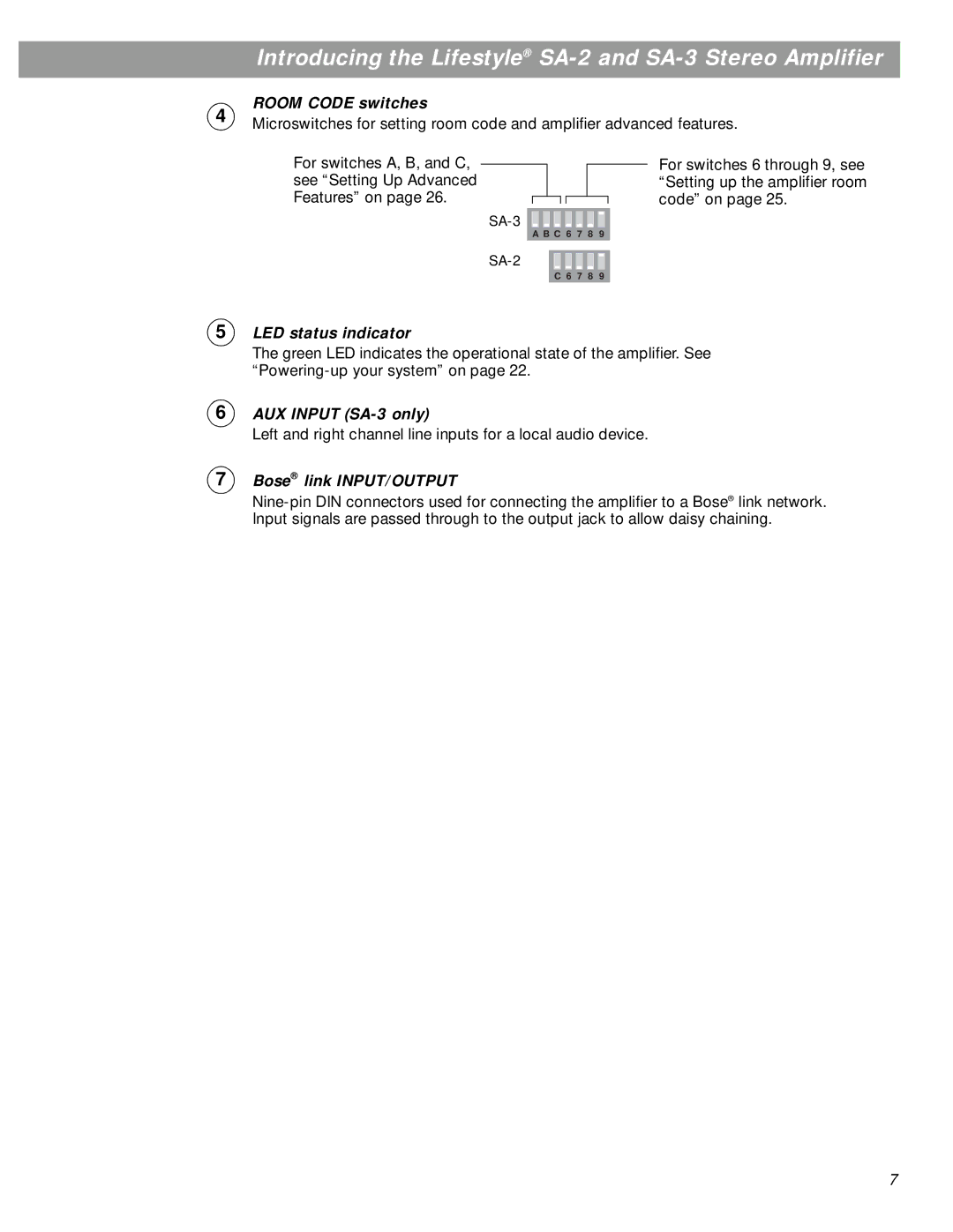
SA-3, SA-2 specifications
The Bose SA-3 is an advanced soundbar designed to enhance your home audio experience with incredible clarity and depth. As a part of Bose's commitment to delivering high-quality sound to consumers, the SA-3 incorporates cutting-edge technologies and features that elevate it above conventional soundbars.One of the most notable aspects of the Bose SA-3 is its sleek and modern design. The soundbar exudes a minimalistic aesthetic that seamlessly integrates into any home entertainment setup. Its compact size allows it to fit conveniently in tight spaces, whether placed on a shelf or mounted on a wall. Despite its small footprint, the SA-3 doesn't compromise on audio performance.
At the heart of the SA-3 are sophisticated audio technologies that deliver an immersive listening experience. The soundbar is equipped with the proprietary Bose Audio Calibration technology, which analyzes the acoustics of your room and automatically adjusts the sound output for optimal performance. This ensures that every note and beat is heard as the creators intended.
Another key feature of the Bose SA-3 is its multi-room capability. Using the Bose Music app, users can easily connect the soundbar to other Bose devices in their home, allowing for synchronized audio playback across multiple rooms. This feature is perfect for hosting gatherings or simply enjoying your favorite tunes throughout your living space.
The SA-3 also supports various wireless streaming options, including Bluetooth and Wi-Fi connectivity. With support for popular streaming platforms, users have easy access to their music libraries, podcasts, and more. The soundbar is compatible with voice assistants like Google Assistant and Amazon Alexa for hands-free control, allowing you to manage your audio experience effortlessly.
In terms of connectivity, the SA-3 offers multiple HDMI inputs and optical audio inputs, making it compatible with a wide range of devices, including TVs, gaming consoles, and Blu-ray players. The inclusion of HDMI ARC simplifies the setup process by enabling audio control through a single cable.
Additionally, the Bose SA-3 includes a customizable EQ setting, giving users the opportunity to tailor the sound profile according to their preferences. Whether you enjoy booming bass or balanced mids and highs, the SA-3 provides the flexibility to achieve your desired audio experience.
In conclusion, the Bose SA-3 stands out in the crowded soundbar market due to its sleek design, advanced audio technologies, and versatile features. Whether for casual listening, movie nights, or gaming sessions, the Bose SA-3 is an excellent choice for anyone seeking to enhance their home entertainment system.

