LOADING THE BTFP12180/BTFP12181
EYE PROTECTION which conforms to ANSI specifications and provides protection against flying particles both from the FRONT and SIDE should ALWAYS be worn by the operator and others in the work area when connecting to air supply, loading, operating or servicing this tool. Eye protection is required to guard against flying fasteners and debris, which could cause severe eye injury.
The employer and/or user must ensure that proper eye protection is worn. Eye protection equipment must conform to the requirements of the American National Standards Institute, ANSI Z87.1 and provide both frontal and side protection. NOTE:
TO PREVENT ACCIDENTAL INJURIES:
•Never place a hand or any other part of the body in discharge area of tool while the air supply is connected.
•Never point the tool at anyone else.
•Never engage in horseplay.
•Never pull or depress the actuating lever unless nose is directed at the work.
•Always handle the tool with care.
•Do not depress the actuating lever while loading the tool.
TOOL ADJUSTMENT CHART
STAPLE
LENGTHS
DIAL
POSITION
5/8" (15mm) | 3/4" (19mm) |
SL
L S
ADJUSTING THE BTFP12180/BTFP12181
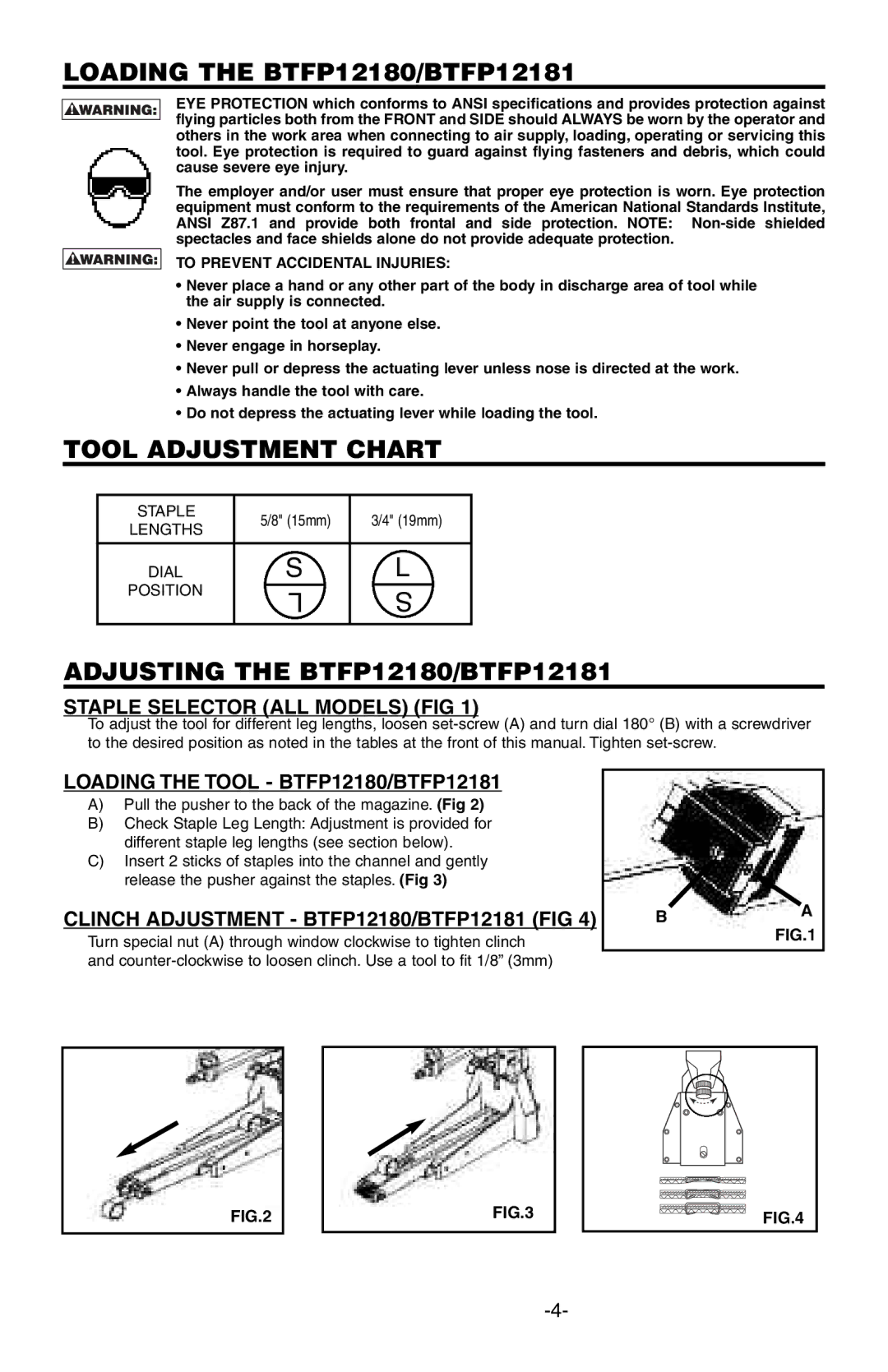
STAPLE SELECTOR (ALL MODELS) (FIG 1)
To adjust the tool for different leg lengths, loosen
LOADING THE TOOL - BTFP12180/BTFP12181
A)Pull the pusher to the back of the magazine. (Fig 2)
B)Check Staple Leg Length: Adjustment is provided for different staple leg lengths (see section below).
C)Insert 2 sticks of staples into the channel and gently release the pusher against the staples. (Fig 3)
CLINCH ADJUSTMENT - BTFP12180/BTFP12181 (FIG 4)
Turn special nut (A) through window clockwise to tighten clinch and
BA FIG.1
FIG.2
FIG.3
FIG.4