Installation—Fuses and Wiring (cont.)
Power/B+ and Power/GND Connection
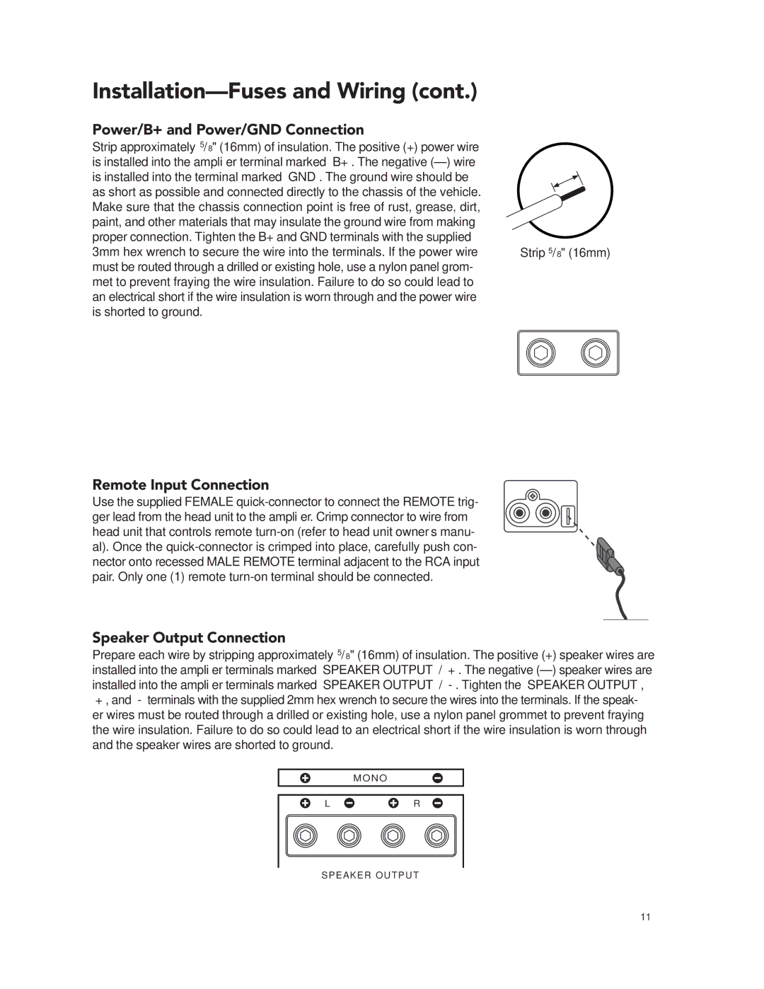
Strip approximately 5/8" (16mm) of insulation. The positive (+) power wire is installed into the amplifier terminal marked “B+”. The negative (–) wire is installed into the terminal marked “GND”. The ground wire should be as short as possible and connected directly to the chassis of the vehicle. Make sure that the chassis connection point is free of rust, grease, dirt, paint, and other materials that may insulate the ground wire from making proper connection. Tighten the B+ and GND terminals with the supplied 3mm hex wrench to secure the wire into the terminals. If the power wire must be routed through a drilled or existing hole, use a nylon panel grom- met to prevent fraying the wire insulation. Failure to do so could lead to an electrical short if the wire insulation is worn through and the power wire is shorted to ground.
Remote Input Connection
Use the supplied FEMALE quick-connector to connect the REMOTE trig- ger lead from the head unit to the amplifier. Crimp connector to wire from head unit that controls remote turn-on (refer to head unit owner’s manu- al). Once the quick-connector is crimped into place, carefully push con- nector onto recessed MALE REMOTE terminal adjacent to the RCA input pair. Only one (1) remote turn-on terminal should be connected.
Speaker Output Connection
Prepare each wire by stripping approximately 5/8" (16mm) of insulation. The positive (+) speaker wires are installed into the amplifier terminals marked “SPEAKER OUTPUT” / “+”. The negative (–) speaker wires are installed into the amplifier terminals marked “SPEAKER OUTPUT” / “-”. Tighten the “SPEAKER OUTPUT”, “+”, and “-” terminals with the supplied 2mm hex wrench to secure the wires into the terminals. If the speak- er wires must be routed through a drilled or existing hole, use a nylon panel grommet to prevent fraying the wire insulation. Failure to do so could lead to an electrical short if the wire insulation is worn through and the speaker wires are shorted to ground.
SPEAKER OUTPUT