CCM7 specifications
Bowers & Wilkins (B&W) has long been synonymous with high-quality audio, and their CCM7 in-ceiling speakers exemplify this commitment. Designed for those who value both aesthetics and audio performance, the CCM7 combines cutting-edge technology with elegant design, making it a stellar choice for custom home audio systems.One of the standout features of the CCM7 is its advanced driver technology. Equipped with a 7-inch aluminum cone driver, it delivers exceptional low-frequency performance, while the use of a 1-inch soft dome tweeter ensures clear and detailed high-frequency reproduction. The drivers are engineered to provide a wide dispersion of sound, creating a more immersive listening experience that fills the room uniformly, regardless of your position.
B&W has also integrated their proprietary Flowport technology into the CCM7. This innovation enhances bass response and minimizes turbulence, resulting in a deeper and more controlled sound. This is particularly impressive for an in-ceiling speaker, where maintaining audio quality can be a challenge. The speaker’s design allows for an impressive frequency response that captures the nuances of your favorite music and movie soundtracks.
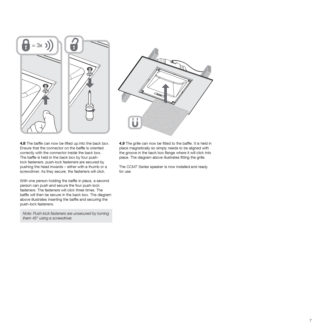
Another notable characteristic of the CCM7 is its minimalist installation profile. With a sleek and unobtrusive design, it can seamlessly blend into any environment. The magnetic grille is easy to remove and paintable, allowing homeowners to customize the speaker's appearance to match their decor without compromising sound quality.
The CCM7 also supports a high power handling capability, making it a versatile option for various audio applications. Whether used alone in a small room or as part of a larger multi-channel audio system, it performs admirably, providing robust sound that elevates any audio experience.
Bowers & Wilkins is renowned for rigorously testing its products, and the CCM7 is no exception. Each speaker is designed to achieve longevity and reliability, ensuring that your investment will provide years of exemplary performance.
In conclusion, the Bowers & Wilkins CCM7 in-ceiling speaker is a perfect blend of advanced audio technology, aesthetic appeal, and practical design, making it an excellent choice for audiophiles and casual listeners alike. Whether you’re looking to enhance your home theater system or create a surround sound experience, the CCM7 delivers the high-fidelity performance that Bowers & Wilkins is celebrated for.

