Braun Corporation FMVSS No. 403 Quick Reference Installation Sheet 34274 Rev. A
3 |
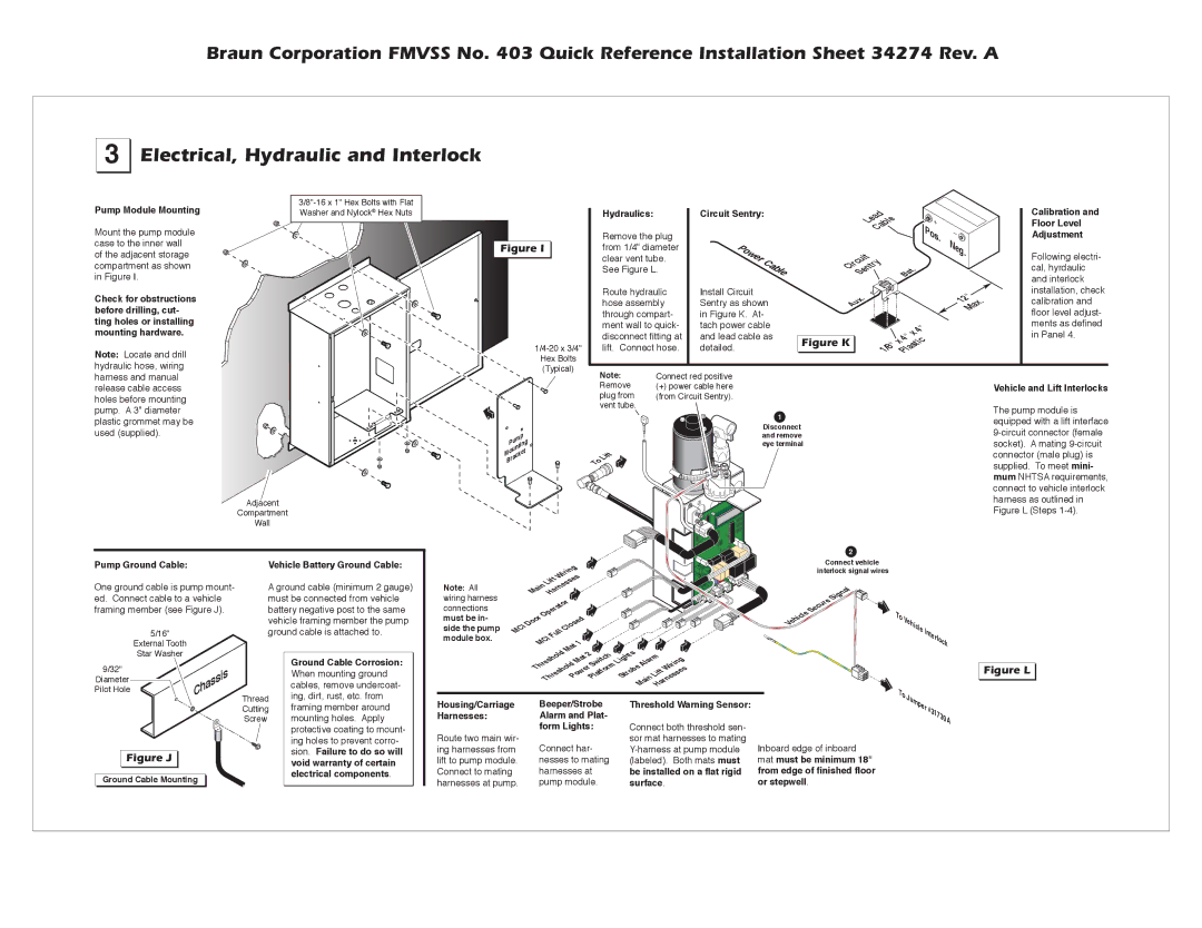
Electrical, Hydraulic and Interlock
Pump Module Mounting
Mount the pump module case to the inner wall of the adjacent storage compartment as shown in Figure I.
Check for obstructions before drilling, cut- ting holes or installing mounting hardware.
Note: Locate and drill hydraulic hose, wiring
Figure I |
Hex Bolts
(Typical)
Hydraulics:
Remove the plug from 1/4" diameter clear vent tube. See Figure L.
Route hydraulic hose assembly through compart- ment wall to quick- disconnect fitting at lift. Connect hose.
Circuit Sentry:
Power | Cable |
|
Install Circuit Sentry as shown in Figure K. At- tach power cable and lead cable as detailed.
| Lead |
|
|
| Cable |
| Pos. |
Circuit |
| Neg. | |
. | |||
| Sentry | Bat |
|
| . |
| 12" . |
Aux |
| Max | |
|
|
| |
|
|
| 4" |
|
| x | |
Figure K | 1/8" | 4" |
|
Plastic | |||
x |
| ||
Calibration and
Floor Level
Adjustment
Following electri- cal, hyrdaulic and interlock installation, check calibration and floor level adjust- ments as defined in Panel 4.
harness and manual release cable access holes before mounting pump. A 3" diameter plastic grommet may be used (supplied).
Adjacent
Compartment
Wall
Pump
Mounting
Bracket
Note: | Connect red positive |
Remove | (+) power cable here |
plug from | (from Circuit Sentry). |
vent tube. |
|
| 1 |
| Disconnect |
| and remove |
| eye terminal |
Lift |
|
To |
|
Vehicle and Lift Interlocks
The pump module is equipped with a lift interface
2
Pump Ground Cable: | Vehicle Battery Ground Cable: |
Wiring |
Lift |
Connect vehicle interlock signal wires
One ground cable is pump mount- ed. Connect cable to a vehicle framing member (see Figure J).
5/16"
External Tooth
Star Washer
9/32" |
|
Diameter | Chassis |
Pilot Hole |
A ground cable (minimum 2 gauge) must be connected from vehicle battery negative post to the same vehicle framing member the pump ground cable is attached to.
Ground Cable Corrosion: |
When mounting ground |
cables, remove undercoat- |
ing, dirt, rust, etc. from |
Note: All wiring harness connections
must be in- side the pump module box.
Main Harnesses |
|
|
| |||
Operator |
|
|
|
| ||
Door |
| Closed |
|
|
| |
MCI | Full |
|
|
|
| |
MCI |
| 1 |
|
|
| |
|
| Mat | 2 |
|
| |
Threshold |
| Lights Alarm Wiring | ||||
Mat Switch | ||||||
|
|
| PowerPlatform Strobe | Lift | ||
| Threshold |
| Main Harnesses | |||
Signal
Secure
Vehicle
To |
|
Ve |
|
hicle | Inte |
| rl |
| o |
| c |
| k |
To |
|
J |
|
Figure L |
Figure J |
Ground Cable Mounting
Thread | framing member around |
Cutting | |
Screw | mounting holes. Apply |
| protective coating to mount- |
| ing holes to prevent corro- |
| sion. Failure to do so will |
| void warranty of certain |
| electrical components. |
Housing/Carriage
Harnesses:
Route two main wir- ing harnesses from lift to pump module. Connect to mating harnesses at pump.
Beeper/Strobe Alarm and Plat- form Lights:
Connect har- nesses to mating harnesses at pump module.
Threshold Warning Sensor:
Connect both threshold sen- sor mat harnesses to mating
Inboard edge of inboard mat must be minimum 18" from edge of finished floor or stepwell.
umper #3 |
1730A |