8.Install ACCM board into transfer switch using supplied screws in locations shown.
Screw Locations
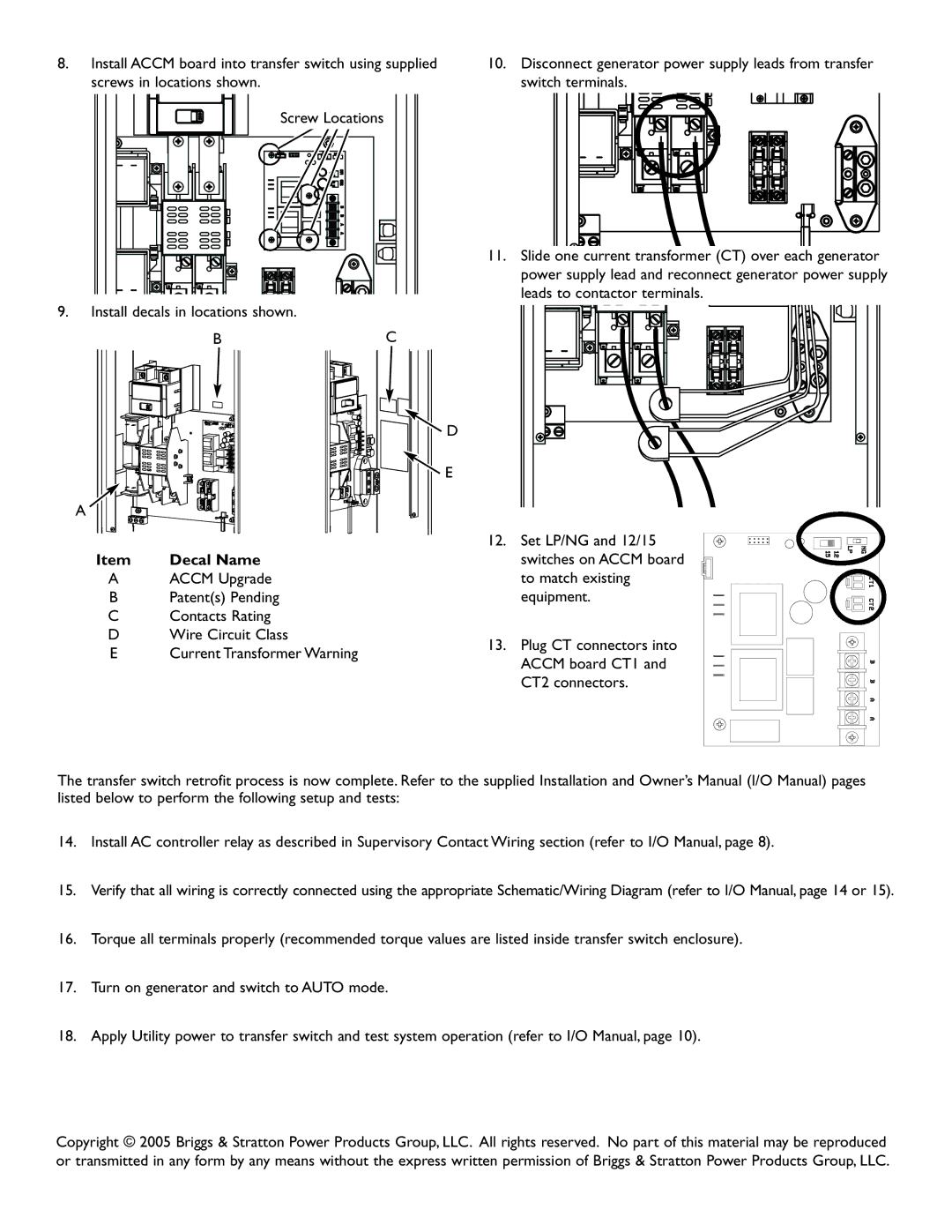
9.Install decals in locations shown.
BC
![]() D
D
![]() E
E
A
Item | Decal Name |
AACCM Upgrade
B Patent(s) Pending
C Contacts Rating
D Wire Circuit Class
E | Current Transformer Warning |
10.Disconnect generator power supply leads from transfer switch terminals.
11.Slide one current transformer (CT) over each generator power supply lead and reconnect generator power supply leads to contactor terminals.
12. Set LP/NG and 12/15 switches on ACCM board to match existing equipment.
13. Plug CT connectors into ACCM board CT1 and CT2 connectors.
The transfer switch retrofit process is now complete. Refer to the supplied Installation and Owner’s Manual (I/O Manual) pages listed below to perform the following setup and tests:
14.Install AC controller relay as described in Supervisory Contact Wiring section (refer to I/O Manual, page 8).
15.Verify that all wiring is correctly connected using the appropriate Schematic/Wiring Diagram (refer to I/O Manual, page 14 or 15).
16.Torque all terminals properly (recommended torque values are listed inside transfer switch enclosure).
17.Turn on generator and switch to AUTO mode.
18.Apply Utility power to transfer switch and test system operation (refer to I/O Manual, page 10).
Copyright © 2005 Briggs & Stratton Power Products Group, LLC. All rights reserved. No part of this material may be reproduced or transmitted in any form by any means without the express written permission of Briggs & Stratton Power Products Group, LLC.