AIR CONDITIONER CONTROL MODULE
RETROFIT KIT
Model 071015
IMPORTANT! The information presented here is retrofit instructions only. Refer to the included Installation and Owner’s Manual for complete safety/hazard warnings and testing instructions.
This air conditioner control module retrofit kit’s components were selected to maximize the utility of a home standby generator system. Full description of this transfer switch operation is described in the included Installation and Owner’s Manual.
IMPORTANT: Installing this retrofit kit with home standby units other than 12KW or 15KW units may result in generator overload and possible equipment damage.
If you have questions about this retrofit procedure, call
The following items are included in this retrofit kit:
•ACCM Circuit Board (1)
•Current Transformer (2)
•ACCM Upgrade Decal (1)
ASSEMBLY SEQUENCE
IMPORTANT:
Intended for use only with 12KW and 15KW home
standby units.
Only licensed electrical contractors should install this
transfer switch retrofit kit.
Installation must strictly comply with all applicable
federal, state and local codes and regulations.
1.Turn generator off.
2.Disable all power to transfer switch.
![]() WARNING
WARNING
Risk of electrical shock or personal injury.
•More than one disconnect switch may be required to
NOTE:The transfer switches shown herein may differ in appearance with the actual transfer switch being retrofitted.
3.While holding ACCM board near installed control board, transfer each signal wire from the installed board terminal strip to the matching terminals on the ACCM board terminal strip.
4.Transfer the six control wires from the installed board to the matching faston tabs on the ACCM board.
5.Remove installed control board and discard screws.
•Contacts Rating Decal (1)
•Current Transformer Warning Decal (1)
•Patent(s) Pending Decal (1)
•Wire Circuit Class Decal (1)
•Loose Hardware:
•This Installation Sheet (1)
•Installation and Owner’s Manual (1)
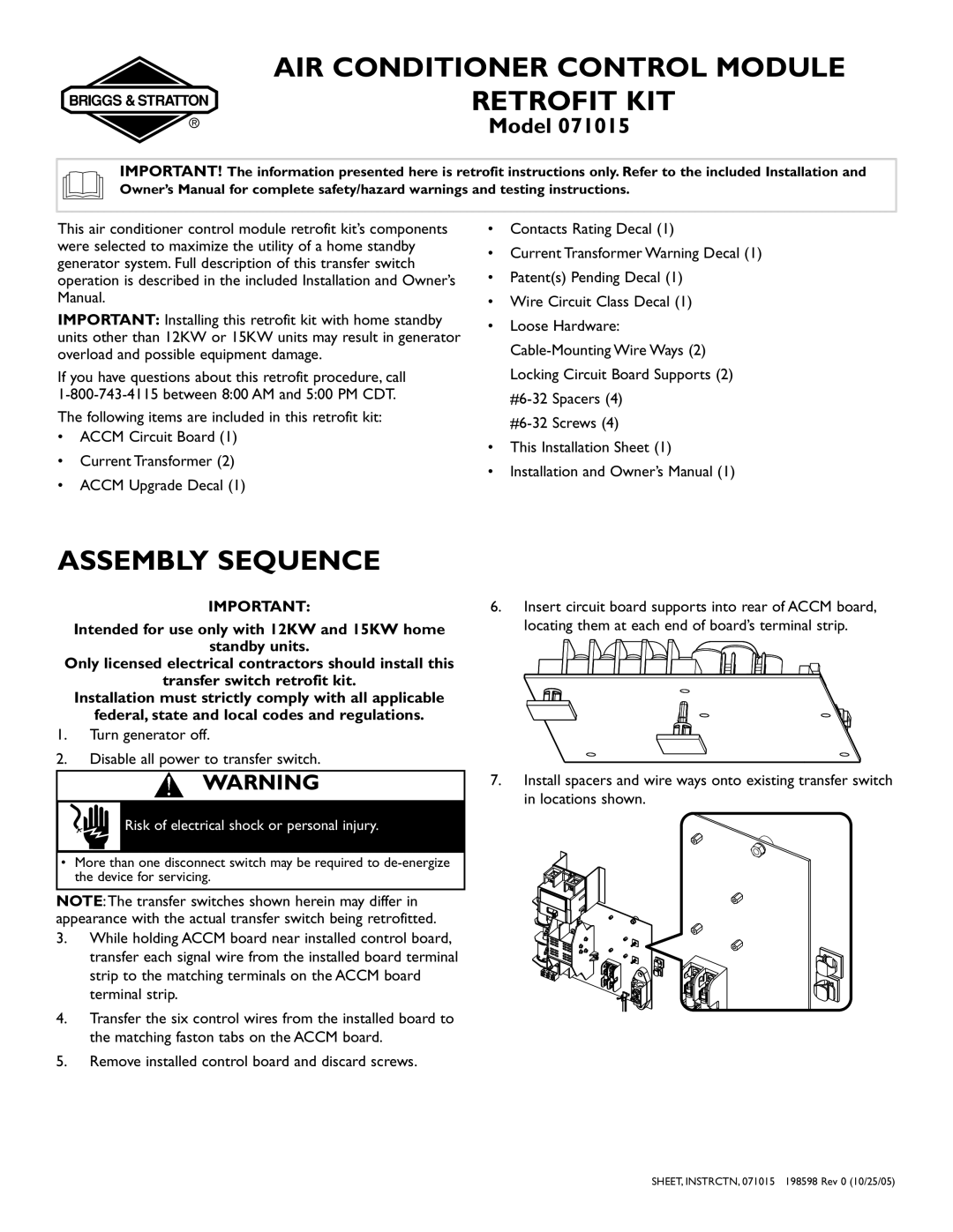
6.Insert circuit board supports into rear of ACCM board, locating them at each end of board’s terminal strip.
7.Install spacers and wire ways onto existing transfer switch in locations shown.
SHEET, INSTRCTN, 071015 198598 Rev 0 (10/25/05)