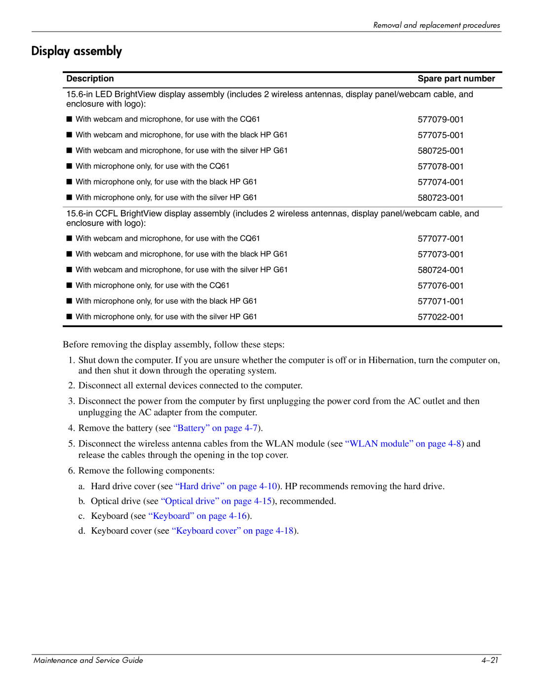
CQ61-310US, CQ61-303XX, CQ61-320EA, CQ61-307AU, CQ61-319WM specifications
The HP CQ61 series comprises a range of laptops designed to cater to various computing needs, featuring models such as the CQ61-306AX, CQ61-328TU, CQ61-325TU, CQ61-318TX, and CQ61-488EE. These laptops offer a blend of performance, reliability, and versatility, making them suitable for everyday tasks and multimedia consumption.The HP CQ61-306AX is characterized by its efficient AMD Athlon II dual-core processor, which delivers solid performance for everyday applications. Equipped with 4GB of RAM, it ensures smooth multitasking capabilities while allowing users to run multiple applications simultaneously. The laptop also features a 15.6-inch display, providing ample screen real estate for various tasks, from browsing the web to enjoying videos.
The CQ61-328TU model stands out with its Intel Core i3 processor, offering a balance of efficiency and power. Its generous 500GB hard drive provides ample storage for documents, photos, and videos, while the integrated Intel HD graphics allow for casual gaming and video playback. The laptop also features wireless connectivity options, enabling users to stay connected wherever they go.
In contrast, the CQ61-325TU is focused on offering a robust performance with its Intel Pentium processor, ideal for users who need a reliable machine for office applications and basic entertainment. With a similar 15.6-inch display and enough RAM to manage everyday tasks efficiently, this model ensures a balanced experience for budget-conscious consumers.
The CQ61-318TX model caters to more demanding users, as it includes a dedicated NVIDIA graphic card, providing enhanced graphics performance for gaming and multimedia applications. Coupled with its dual-core Intel processor and expansive storage options, it is suitable for those who require a laptop that can handle more resource-intensive tasks.
Finally, the CQ61-488EE rounds out the series with a focus on durability and user experience, featuring high-quality materials and a comfortable keyboard design. Its hardware specifications strike a balance between performance and energy efficiency, making it an attractive option for business professionals and students alike.
All models in the HP CQ61 series come equipped with HP's suite of technologies, ensuring reliability and functionality. With their diverse range of specifications, these laptops address various user needs, making them a versatile choice in the competitive laptop market.

